Pages

Thursday, February 20, 2014

GHERKIN SNIPPET

I'm on a roll, working up my Gherkin studies as Teaching/Learning resources for anyone who might want to have a go at using a BIM approach to research / private study / figuring stuff out.  curiosity is a wonderful thing and BIM tools like Revit have tremendous untapped potential for fostering the investigative skills of students, both young and old, around the world.
So here's a little taster from my current "work-in-progress" model.  I've been adding the cladding that covers up the tubular steel structure.  I'm exploring the idea of being able to switch this on and off so that you can peel the onion gherkin layer by layer.  It's a render & a shaded image combined with a smidgeon of jiggery pokery to enhance the effect.  (2 layers, shaded on top, overlay mode, slight use of masking to vary the transparency)


By the way, I would love to get some more feedback.  I'd love to know how this stuff is getting used.  I do hope I can encourage more people to see BIM as an educational tool and not just another cog in the global "business machine".

Sunday, February 16, 2014

GHERKINS FOR ALL

This is the second post in a series.  I am trying to encourage students & teachers of Architecture & Building to use BIM as an active research & learning tool.  It could be a Drawing course, a Technology course, a Theory of Design course, a History of Architecture course, or even a BIM module :-)  The idea is to take an integrated approach.  Don't teach Revit with a series of abstract, disconnected exercises.  Use Revit as an investigative tool, as a way to learn other stuff.  Use it like you might use a pencil, exploring the way something works in a series of freehand sketches.


In this post I am presenting the first two passes of an exploration.  There is a Revit file to download, and a set of handouts or "summary sheets" to guide you through the process of creating this file from scratch.  The models you create will be abstractions: simplifications such as architects commonly use when analysing a design idea.  We are trying to capture fundamental relationships, underlying concepts and geometries.  In the next post we will be adding more subtle inflections, coming closer to reality.  But my focus will always be on the learning experience. 


The summary sheets show the main steps.  I'm trying to cater for fairly new users, but not for absolute beginners.  If you have no experience of Revit at all, you will need a guide, someone with more experience.  They are designed to be useful to someone leading a class.  I'm hoping it will reduce your preparation time.  If you have intermediate Revit experience, you should be able to work through the exercises once yourself, then launch straight into teaching, using the sheets as handouts.


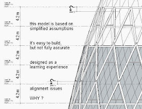
I'm using a floor to floor height of 4.2m  This is almost certainly incorrect.  But it's not far off, and it's a convenient round figure.  I don't want you to be distracted by irrelevant details.  We're using a broad brush approach to gain some basic insights.  Similarly I have chose to offset the 3 shells (see previous post) by half a metre from each other.  This is surely wrong, but it makes the maths much easier and it works fairly well in practice for the models we are building.


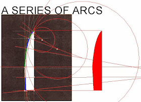
I received a comment on my last post, pointing out that the Gherkin was conceived as a revolve, rather than a loft.  I'd like to thank Mwaraya for this contribution.  It's great to get feedback and I individuals or groups who use this material will contact me with more comments and corrections.  I will do my best to respond and improve my work.  It appears that the Gherkin profile was conceived as a series of arcs in section.  My lofting approach comes very close to the same shape, but is fundamentally quite different.


An analogy may help.  When setting out an ellipse, builders commonly use an approximation base on arcs.  This is easer to construct on site than a true ellipse.  Similarly you could approximate a parabola with a series of arcs.  Gaudi used a different approach, creating catenary curves by hanging chains and cloth, then freezing the result as a plaster cast.  It's a question of choosing the method to suit the situation. 


In my case, lofting from a series of circles is a very economical approach to generating 3 concentric Gherkin shells, my Russian dolls representing Skin, Frame & Floors.  I would also venture to suggest, that although the architects my have conceived the original form as a series of arcs constructed in section, the real building was not set out like this.  It was constructed from tubular steel A-frames, each 2 storeys high.  18 of these frames form a complete ring, leaning inwards or outwards slightly depending on the location.  In this sense the Gherkin is lofted from a series of circles, even though the diameters of these circles may have been decided by constructing a set of arcs in section using a CAD programme.


As for the skin it is neither a revolve nor a loft, but a large number of diamond-shaped facets, each perfectly flat.  (in as far as glass can be said to be perfectly flat)  It seems to me that this is a rather special type of unitised curtain wall system.  Each diamond is one story high and must be fixed back to the steel frame in some way.  There must also be a system of adjustments and tolerance allowances.  It would be fascinating to know more about how all that works.


In practice many of the diamonds are split into triangles by transomes that coincide with the floor slabs.  Some of these triangles hinge out to provide natural ventilation in hot weather.  Once again my Revit models diverge from reality slightly.  I am using a Rhomboid divided surface.  Triangles occur at the edges of the surface, but not at each floor level.  The illusion of triangles will be created by having a slab edge that penetrates the skin, appearing to divide the glass.


As long as we are aware that our model diverges from reality everything will be fine.  Problems arise when people start to imagine that CAD & BIM allow you to create "reality" inside the computer.  It's no more real than a pencil sketch.  It may be more complex.  It may capture more aspects of reality.  But it's still a model, an abstraction.  It's important to remember what we are abstracting and why.  Blindly modelling every nut and bolt, "just because we can" is a recipe for disaster.  Be aware that you are simplifying.  Think carefully about what you want to achieve.  Choose appropriate methods, including shortcuts and assumptions.  Structural Engineers make stick models.  They assume that joints are either rigid or perfect hinges.  This is not the case, but it allows them to do their job effectively.


You can download the various files from the Autodesk 360 links below.


Basic Geometry diagram           http://a360.co/1liJ69v

Summary Sheets                      http://a360.co/1ghYwHW

2nd pass Revit Model               http://a360.co/1lPQQDH

More developed Revit model    http://a360.co/1ghYsb9


Monday, February 3, 2014

GHERKIN REVISITED

I am revisiting the Gherkin following a request from David at the University of Ulster.  He wanted to share my Revit model to use with his first year Architecture students.  As usual I felt it was necessary to clean things up again before uploading, and learnt quite a bit along the way that seems worth sharing.

So the idea here is for a research project using BIM processes.  It's a learning experience for students of Architecture, or just anyone who is fascinated by what makes buildings tick.  It's supposed to be hands on.  You model the Gherkin in Revit and you get a much deeper insight into the design & the technology along the way.  Also maybe learn some new Revit skills.  There are several earlier posts you might want to flip through.  Just type "Gherkin" into my search box and you'll get a list of links something like this.


Design is a bit like calculus.  You start with a rough approximation, which then points the way to a more exact definition, leading to something closer still, and so on.  As the iterations increase, you get closer to your goal.  When I was at school we called it tending towards infinity. So I'm going to start with a broad brush interpretation of the Gherkin & when you understand the geometry of that we'll start to introduce various subtleties to draw you closer & closer to the actual thing.  We'll never actually get their of course.  It's just a learning exercise.


So let's get to it.  We will treat the building as a set of Russian dolls representing the glazed skin, the diagrid steel frame and the floor plates. The first two will be half-dolls in order to reveal what's inside (and to save on processing load)  The two halves will be rotated at 90 degrees to each other to even better see the relationships between the 3 major elements.


I'm not going to describe every step in the process here.  Instead there will be a pdf "handout" to download.  Getting into teacher mode here.  There will also be a download of the Revit file.  Be patient it may take a couple of posts before the downloads are ready.  Here are the parts, shown separately and then combined.  This is the first approximation.


Each of the shells is made in the same way.  A series of circles with different radii and vertical offsets are used to loft a form.  Revit has a habit of breaking circular volumes into two halves.  You can see the seam in the image below.  Using "tab select" you can pick one of these curved surfaces and divide it.


Divided surfaces start off as a 10x10 grid, but then you can change the numbers (U & V) and you can also select a different pattern.  We will be using "Rhomboid" in this first exercise.  Later we will use "Half-Step" for the structure.  For the frame we need an 18x18 grid, for the skin 72x72. It's a bit more complicated than that, but we'll get to that later.  4 panes of glass for each leg of the frame.


Next step is to make simple curtain panel families.  I keep them simple as possible, because when you load them the computer is going to go into thinking mode for a couple of minutes.  Don't want to overload systems which may not be state of the art.  The structural skeleton is based on "A frame" components bolted together.  I came up with a family that fits an "A frame" into the top half of a rhombus with no geometry in the lower half.  That geometry will be provided by the row below. 


This seems to work, but later on we get a slight anomaly when the family is loaded into the project.  You get an extra "phantom" row at the top.  Basically Revit has to chop edge panels in half (making them into triangles)  When it cuts the bottom off an A frame it is cutting "nothing" away.  This seems to cause confusion.  I should mention the floor faces.  For simplicity I start with 40 levels, all equally spaced, 4.2m apart. That will do for the first pass.  Most of these levels get a floor face, but there's a double height ground level and some plant floors near the top that don't follow the gherkin shape.

The next image illustrates the "second pass" as we build a bit more sophistication into the model.


Firstly, the skin is lofted in two parts: the "main body" and the "top cone". The grid is relaxed from 72 divisions to 36 in the top cone.  I guess this is to avoid very small panels at the top as the diameter gets smaller.  Secondly we need to tab-select individual components and modify them.  There is the very tedious task of swapping clear panels for black ones.  You can see that I am half way through this task in the image above.  The result is a spiral effect which hints at the presence of voids behind the glass.  Also some of the skin panels need to be deleted at the base to create an open "colonnade" at ground level. 


The spiral voids are very interesting.  Basically we have 9 "A frames" in our half-gherkin structural shell.  That's 20 degrees per frame.  And there are 4 floors per structural rhombus.  In other words the glazing panels are one storey high.  This is very clear in the picture above.  Divide 20 by 4 and you have a 5 degree rotation per floor level.  I'm talking about the black spiral bands. 


There are triangular voids that follow the spirals.  Use a shaft opening for the first one.  Create a radial array with 6 of these and group the whole thing.  Copy to clipboard and paste aligned to the next level.  Rotate this second group by 5 degrees.  Repeat the process.  Every sixth floor remains complete as a fire break.


To solve the "A frame" anomaly I switched the pattern type to half step.  This is like stretcher bond in brickwork.  That's a more accurate abstraction of the way the A frames work.  Each row is offset half a grid compared to the row below.


You also need to make a curtain panel family based on the same pattern.  Select the grid within the family template and change it to whichever pattern you need.  That's a step that people often miss when they first start making pattern-based panels.  You'll see that I've been tweaking the top cone: splicing in a zig-zag join, adding some bits and pieces like the glass dome at the top and the rails for the cleaning system. 


But I want to finish this first overview post with a snapshot of my "geometry analysis" page. Later on this will be available as a higher resolution pdf download.  There will also be a more detailed stepping through of the processes to build these analytical models of the Gherkin.  And of course the actual Revit model will become available. Give me time :-)