Pages

Thursday, January 16, 2020

GREY STORY 5: NEW FEATURES & TOILETS


Continuing with the story of my blog.  April 2012 and I had been doing some interesting work on a project in our office.  In those days I was trying very hard to convince the “designers” that Revit could produce compelling images. My go-to method involved combining shaded & rendered images with the same resolution in Photoshop, then using transparency, masking & filters to achieve “artistic” effects.  Part of the trick is to limit your processing time to 10 or 15 minutes so that the images are repeatable when the model changes.


I backed this campaign up with demonstrations of the power of a “single building model” to rapidly generate multiple view types which can be arranged on a sheet to explain a sub-assembly and progress detailed design work.  Problems can be solved more effectively because all the views update in sync as the design is refined.  


One of the images here shows a particularly thorny design puzzle involving headroom under a ramp and structural alignment/continuity.  The relatively new ability to assign transparency to elements proved helpful here.


https://grevity.blogspot.com/2012/04/snapshot-of-today.html


I have always seen my blog as slightly different from the “tips & tricks for Revit” style of blogging.  But from time to time I have posted about technical issues, and in this case I was commenting on the release of Revit 2013.  Interesting to read this again.  People were complaining about the lack of “game-changing” new features and I used an evolutionary analogy to argue that the small productivity improvements may be what allows BIM to survive in the face of considerable skepticism (8 years ago) and that if you don’t survive you can’t go on to deliver the game-changing new features which eat up a lot of development time and money.


Carl Bass was preaching the “Cloud, Mobile, Social” mantra in those days and those three elements have certainly grown in importance in my work here as it went through the Pumpkin era, Project Soane, and now Notre Dame.  Our work on Notre Dame would be inconceivable without BIM360 & Slack for example.  In 2012 I was hoping that Showcase would be the viewing engine that would allow Revit to undercut the Sketchup guys.


Could this finally be the viewer that works ?  I’ve tried Design Review & Navis Works Freedom,  Quicktime FBX plugin, Tekla Bimsight ... People are doing clever things with Game Engines, but I need a quick and easy way of bringing a lightweight export from the model into meetings.


Well that was a disaster, but in a way it pointed us towards Enscape3d which has been a resounding success, prompting Unreal & Unity to become serious contenders also.


https://grevity.blogspot.com/2012/04/broad-brush-fine-detail.html


So I got my hands on the new release and spent a couple of weekends trying out the new features. Of course the new stairs & railings are still a source of disappointment.  “why doesn’t everything just work the way you want it to?” people say.  If we were capable of perfection, I think I would start with world poverty, not Revit, but in truth I remain optimistic on both fronts.  


I went on an interesting detour into the interface and how it would be great to be able to “teleport” to relevant settings sometimes instead of aborting what you are doing to create a new arrow style or profile.  These thoughts eventually morphed into a whole presentation I did at RTC Washington in 2015 called “Sharpening the BIM pencil” starting with the little things that annoy me about the Revit interface and gradually broadening out to reflections on the wider BIM landscape.  I should do a couple of posts on that some time. (only 5 years too late)


https://grevity.blogspot.com/2012/04/playing-with-my-new-toys.html


The next post is fascinating.  I suddenly started to see the “Show Workplane” feature as something like the UCS was when I used CAD.  Does anybody use workplanes like that?  I dabbled for a weekend but it never caught on.  I do occasionally show the workplane, or set it to a surface, but it’s not become a regular part of my workflow.


https://grevity.blogspot.com/2012/04/catching-plane-to-work.html


And so we come to “parts”.  Once again I had high hopes, and I guess there are people who use parts all the time.  I think it would be interesting to do some studies on Notre Dame using parts to set up views where the construction layers peel back, as in this post here.  But the truth is that I very rarely use these techniques in practice.  Maybe I’m just lazy.


https://grevity.blogspot.com/2012/04/breaking-up-is-hard-to-do.html


There have been lots of toilet posts over the years.  There is much better content available for plumbing fittings now, but back in 2012 this was one of my pet peeves, and I have to say that my reaction was mostly to try to show how the problem could be tackled, rather than waste my time complaining.  I agree with Marcello Sgambelluri on this.  The factory has given us a foundation, it’s up to us to show what we can build on top of it.


https://grevity.blogspot.com/2012/04/my-weekend-on-toilet.html


And another post along the same theme.  I tried very hard to create acceptable urinal geometry using Revit and Autocad to generate solids.  These days I would probably find a mesh object on the manufacturer website and hide the edges in Max.  Quite possible one of the “content providers” will already have done this for me by now.  But back in 2012 it seemed like the best way forward was to try to build this stuff myself and to share my efforts on this blog.


https://grevity.blogspot.com/2012/04/more-punishment.html


A new feature crept into point world with Revit 2013.  What could I do with “divide & repeat”  Zach Kron hadn’t yet morphed into “Dynamo man” so he was giving us some of his funky posts about this new feature.  My mind was running in a slightly different direction.  I ended up with a series of objects that looked like a cross between a UFO and a Luigi Nervi sports stadium.  Playing with the new visual styles and subconsciously choosing the right colours I found myself in some kind of “Rupert Bear World” which brought back all kinds of childhood memories.


https://grevity.blogspot.com/2012/04/first-division.html


I’m quite amazed that I managed to create 9 posts during April 2012.  Normally I would manage between 3 & 5 per month.  Basically I have settled into the “long form conversation” type of blog-post, based on a couple of days doing stuff in Revit (mostly) then best part of a day compiling/formatting images and writing a story that links them all together.  


When I switched to a 4 day working week (at age 65) my intention was to increase the number of blog posts.  To some extent that has happened, but the intent has been undermined by my commitment to large, complex modeling exercises (Project Soane & Project Notre Dame).  I   made several attempts to create shorter, more focused posts, but the longer form seems to creep back.  I wonder what happened in April 2012 though.  Were there some long weekends in there?  Did I just have a backlog of unfinished posts?


Anyway, let’s finish this.  I wanted to create a shade structure.  These are commonly used for children’s play areas here in Dubai because the sun is really fierce.  We have used this family on real projects, a couple of times.  It’s a bit of a cheat because the surface is perfectly flat, it doesn’t sag.  Strangely enough, our brains are expecting to see the effects of gravity, so you don’t really notice the flatness from most viewpoints.  The curved edges are sufficient to fool the eye.  If I was making this again I would be able to introduce a “sag factor”.  But at the time, my “point world” skills were still somewhat tentative.  


Actually, I rarely use point world these days.  I don’t like the fact that you can’t make the families “work plane based”.  They won’t attach to a level and respond to an offset from that level which is such a basic feature in most everyday work.  The only way around this, as far as I know, is to use the Mass category, which leads to a different set of disadvantages. 


https://grevity.blogspot.com/2012/05/sailing-free.html


Sunday, January 12, 2020

ADJUSTING TO REALITY


We still have no access to point cloud data for the cathedral.  Fortunately we have the TruView site that was placed into the public domain by Leica shortly after the fire.  Gradually we have figured out how to adjust the “Z” coordinates of picked points to align with our Revit model.  


It’s a little bit tedious, but we can record these values on screenshots and on section/elevation views.  It seemed prudent to create a lightweight file with a copy of the grid and place scaled jpegs in section views,  fade the image with a semi-transparent masking region, and draft over a revised setting out for the major elements.  Within this study file, we have set the shared coordinate system to read out the TruView Z coordinates.  The TruView zero is basically a tripod height above the triforium gallery floor.


Two types of spot elevation can be used to report both the TruView & model coordinates for any given point.

Based on this analysis we have been able to adjust various elements, dropping the sill heights of the clerestory windows running around the chancel at high level. (it seems that they are systematically lower than those of the Nave, by about 750mm)  The adjacent “flat” roof and parapet railing were also dropped, while the sloping roof over the outer aisles has been given a steeper pitch and raised a little.


At the internal corner where the chancel meets the transept there is a round column. This has been represented by a placeholder family, to be elaborated by whoever claims the task.


My role in the team has been to push ahead with this kind of  “roughing out”.  As my original placeholder families are replaced by others, the “technical views “ that Revit updates constantly for us begin to come to life, stimulating our imagination and asking penetrating questions.


Gradually the cathedral becomes more and more familiar to us, like an old friend

For example, the triforium roof alongside the nave was very puzzling some months ago but is now a suitable subject for explanatory diagrams as we start to tell our stories more clearly.


By taking measurements in TruView across groups of buttresses it has been possible to confirm an exercise I carried out some months ago based on a jpeg plan from the point cloud. This implies a number of adjustments to the grid.

Personally I think we should continue our strategy of straightening up the building and keeping all the elements aligned to a regular, orthogonal grid.

Ultimately this is a judgment call based on our mission to create a study model for didactic purposes and to place the results of our explorations in the public domain. Ours is a parallel effort to the model being built by the construction team which necessarily must model each element individually and reflect the minor deviations that occur on site for a variety of reasons.  By contrast, we are creating a somewhat idealised and simplified model of Notre Dame; trying to uncover the underlying rationale.


I think the two efforts are complementary in the struggle to understand what this ancient monument means to France, to students of architecture, to BIM addicts and heritage workers of various kinds, to devout Catholics and to the general public all around the world many of whom have vivid memories of tourist visits to Paris in the years before the fire.


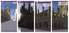
A mobile friendly model would be great. In that vein I tried the Enscape3d Web standalone on my android phone. It may be me but I couldn’t figure out how to walk around.


A quick upgrade next, to arches at the base of the Bell Towers where it connects to the nave and aisles. Adjusting widths and editing the profile to replace the sharp edges with reeding.


The transept ends need a lot of work not least to define the voids inside the thickness of the wall that connect the spiral stairs to various visible doorways. Not surprisingly, the wall joins get in a bit of a tangle when trying to model something of this complexity.   We really need someone to take ownership of this area and build it more systematically.  

But before attempting this, perhaps we need to adapt to the revised grid so that we don’t end up doing everything twice.


Just to complicate things the rose windows needed to be lifted by about a metre, which makes the relationship to the vaults behind much more sensible, but requires multiple adjustments to adjacent elements.

And finally, the gables above. Waiting for Marc to finish the North Rose, so using the South version as a temporary placeholder.  Below that small rose a length of railing above an in-place sweep, and atop it all, a simple coping to “finish” the steep slopes that define the top of the gable.  More to do to elaborate this, but at least it’s starting to catch up with the rest of the model.


Sunday, January 5, 2020

MODELS GALORE


Picking up on my previous post where I commented on a model shown of French TV, I am prompted to wonder how many independent teams have be asked to make a model, by whom and for what purposes?  Clearly there is great public interest in the Notre Dame story, and 3d animations are stock in trade for the media these days.


An article in the NY Times popped up in my LinkedIn feed which features yet another model (I don’t think it’s the same one)  I would hazard a guess that any number of media studios would be willing to knock up a quick animated model of Notre Dame without needing to think too deeply about the spatial configuration or the technicalities of construction.  If the aim is simply to highlight the location of various events, there is no need to take a BIM approach or to puzzle your way through the finer details of its complex geometry.   So well done to all concerned: a fascinating story, well presented.


https://www.nytimes.com/interactive/2019/07/16/world/europe/notre-dame.html


But it’s interesting for me to spot the simplifications and omissions in these models.  Once again, the the subtleties of the triforium gallery have eluded the modeling team.  The roof at both ends should pop up to a higher level (a memory of the original design when the clerestory windows were much smaller)  


Where the galleries abut the transept they should turn the corner, all 4 corner in fact.  This is difficult to spot at first because of the stair towers and buttresses that adorn these corner, each one slightly different in configuration.  Quite why these difference occur is beyond me at present, as are many other small anomalies and inconsistencies that continue to arise as we delve deeper and strive for greater accuracy and understanding.


Meanwhile, Dinos has taken our model into Twin Motion and created a quick executable which is quite interesting as a supplement to those we have been producing with Enscape3d.  I think I prefer the architectural qualities of the Enscape visuals, but there are some positives in Twin Motion, the animated people and the ability to vary the weather, for example.  


I’ve taken advantage of some of the dramatic weather effects to generate some atmospheric views, with a bit of jiggery pokery in PIXLR.


I’m not sure where the sky box came from but it’s very effective.  Glimpses of a suitably European skyline on the horizon.  However, I find myself wondering now what we want to do with imagery of this sort.  What kind of story do we want to tell about Our Lady?  Is it sufficient to interweave these atmospherics with more technical views, or do we have to add diagrams and animations? 

Certainly we can explain the subtleties of the Triforium Gallery and tell the story of the insertion of larger clerestory windows in the 60 central bays of the nave, a century or so after the original construction.


We can also describe the offset centre-point of the apse curvature and some of the subtleties of the resulting geometry.  We can talk our audience through the many varieties of rib-vault found when scrutinising the reflected ceiling plans (how the geometry works, how to build them in Revit). 

Perhaps we can look more closely at certain typical details.  Show how the individual stones are shaped and fitted together.


But what else?

What tales of faith, passion, blood and passion can we tell to rival the tales of Victor Hugo, the figure of Quasimodo?  How do we tell the story of all the stone carvings and sculptural embellishments?  Do we extract these mechanically from a point cloud, or invite digital sculptors to create their own versions?  Who are those figures in the gallery of kings stretching across the west façade?  Are they mythical, historical, or a mixture of the two and what morals are we intended to draw from their inclusion in such a prominent location?


Time will tell.  Maybe you have some ideas.


Saturday, January 4, 2020

ROARING TWENTIES HERE WE GO


This will be my (last post of 2019) first post of 2020


An image of me on stage at Autodesk University Middle East.  That was a great event.  Those who have shown an interest in taking part in Project Notre Dame, please be patient, we haven’t forgotten you.


I uploaded my presentation so that should be coming up on the Autodesk site before too long.  In the meantime you can download a precis of my talk at the link below.


https://drive.google.com/file/d/1Olsu-dThzWzQMWMCQKL_u4oVX6Vk8_ez/view?usp=sharing


And here's the video

https://www.youtube.com/watch?v=teKDOurIb6U


Over xmas, I put a bit of work in on the chancel.  The raised floors and steps were roughed out very rapidly for AU Las Vegas, so I went back and adjusted levels.  Also looked a bit more carefully at where the various sculptural elements are placed.  We need a couple of kneeling kings and a Pieta (mesh objects) to make this more convincing, but it’s improving steadily.  Ryan is taking a look at the choir stalls, so I’m looking forward to saying bye-bye to another of my “broad-brush placeholders”.


The imagery coming out of the Enscape 3d plug-in is amazing as usual, but perhaps we should also give a nod to the hidden-line views in the sheet set.  This is a classic architect’s approach to conveying information in a crisp and measurable format and of course these views are updating automatically as we add detail and adjust proportions in the model.  Kudos to Alfredo again for his clever cutaway views.


Having said that, I couldn’t resist some foreshortened perspective views to accentuate the drama of this sacred space. 


We still don’t have access to any point cloud data, which is getting a bit annoying to be honest.  The TruView site that was placed in the public domain is really useful, but the Z coordinates that this reports are relative to a tripod positioned up on the triforium gallery, so it take a bit of calculation to relate these to Revit levels and offsets.  I have set up a file to keep track of this, establishing a survey point at the tripod height so that we can compare project levels and survey levels using two types of spot coordinates in Revit.  A bit tedious, but what can you do?


I spent a couple of days carefully adjusting arches and vaults so that the ribs sit on top of their columns and pilasters, plus fit together closely in both directions.  The vaults I am using at present don’t have curved ridge lines.  Maybe Alfredo will remedy that eventually.  For the moment I am concentrating on getting the ribs to fit together nicely as they sprout off in 8 different directions.  

Getting inside the space with my VR headset on is particularly useful to spot gaps and misalignments.  The worst cases now are around the base of the Bell Towers.  Lots of one-off conditions here.  Will take another weekend to sort that out.


Finally, something popped up on Linked-In that is worth a comment.  Obviously, we are not the only people inspired to model Notre Dame.  There is an official BIM model being constructed for the restoration project.  It serves a different purpose to ours and is unlikely to go into the public domain.  But there are also several mesh-models floating around.  Apparently one of these appeared on French TV as an Augmented Reality model in the studio.  


Again, the intended purpose of the model is important.  It was there to focus a discussion and indicate locations where temporary shoring is being used.  It was a news report, not a long-term historical study like ours.  So it would be unfair to comment on the accuracy of the model, except to note that they have made the usual “mistakes” like missing the way the triforium galleries turn the corner at the transepts and the smaller window types at both ends of the nave.


No big deal, but I feel vindicated …  “study history with BIM”