Tuesday, June 4, 2013

MAKING GLASS ONIONS

This one started as a "how can we make this" query from one of my guys.  We sat down & did it on the spot.  Turned out to be quite easy.  The challenge was to make a dome with a ribbed pattern.  This kind of thing is quite common in the Gulf Region.  It's interesting because what seems like a simple arc in plan turns into a more complex curve when mapped onto a spherical surface.


I started with a generic model family and created a hemisphere.  Just a simple revolve.  Then cut into this with an eye-shaped void.  The sketch comprises two arcs starting at the centre of the sphere and ending on the circumference.  This creates two edges.  We can use one of them to create a sweep using the "pick 3d edge" option.  I used a circle for the profile, always the simplest approach when testing a new idea.


Now you can select the sweep and create a radial array.  You might want to leave it there, or you can take the next step, mirror the sweep and create a second array.  Once you have what you want, you can drag base of the void up so it no longer cuts the dome.  I could have deleted it, but I thought I might want to go back and retrace my steps.


As a further exercise I deleted everything except a pair of sweeps then saved this as a component.  Nested this into another family and arrayed it around.  This gives extra stability and you can parameterise the no of elements.  Would be nice to set the radius of the dome as a parameter too, but I'm not sure that's possible with this method.


The second part of the post is quite different, but also has to do with domes.  For this one I have to credit Marcello for the original germ of an idea.  I have been thinking about combining his morphing idea with my scalable rectangular rig.  During the early hours of this morning I had the idea of a parametric dome family where the curve of the revolve can morph between two curves.  During lunch hour I was able to flesh this out a bit.


Start with a rectangular rig, it has width & height parameters.  Add some horizontal rungs.


Now you can drape 2 splines across these rungs.  The curves need to be different in character.  Create another set of rungs between these splines.  Host points on these and link them all to the SAME normalised curve parameter.  Spline through points.   Now you have spline 3 and which is dependent on splines 1 & 2.  Set the NCP to zero and it will lie on top of spline 1, set NCP to 1 and it will shift to spline 2.


I called my NCP "curve factor" and I also added a "Base R factor" .  This is another NCP and it controls the 3 points at the bottom ends of the 3 splines.  These all lie on top of each other.  Maybe I could have had all 3 splines sharing the same point, but the way I made it I kept the points separate and just brought them together at the end.  I used instance parameters throughout so I could lay out a grid of domes and vary the parameters in a systematic way without the bother of naming a whole bunch of types.


The row nearest to us shows the morphing behaviour, going from zero to 1 in 5 equal steps.  The next row is a copy of this with the height increased.  The third row is another copy with the base pulled in to a narrower diameter.

Sunday, June 2, 2013

SPLINE SAILING

I'm writing this in my sister's apartment, the day before I fly out of New Zealand.  I have fulfilled my three-fold purpose: attend RTC, spend time with Ruth & Dave, get to know NZ a little.

RTC was brilliant:  meeting old friends, making new ones; talking, learning, sharing.  Too many names to mention them all, but Alfredo Medina was kind enough to send my the photo below & it was a great pleasure to meet him in the flesh & become friends.  You should check out his web site if you don't already know it.  http://www.planta1.com/forum/blog.php


But let's get down to business.  This post is partly inspired by one of Marcello's sessions.  He made the bold claim of being able to scale "anything" in Revit, which was enough to get me into his session.  My take on this is that he has once more come up with some very interesting techniques which we can each take away and apply in different ways.  They are not "silver bullets".  They don't make all your problems disappear by magic.  Perhaps the most important message to take away from one of his sessions is that there are hidden treasures in Revit, undocumented capabilities that you can tap into if you adopt a positive, "can do" mentality.  His enthusiasm is certainly infectious & it was great to spend time with him again.

Splines are a good example of the "under-documented" nature of Revit.  In a way it's all there in the wikihelp.  The clip belowexplains a behaviour that eluded me for 3 or 4 years before I picked it up on Steve Stafford's blog.  But it's written in such a bland way that you can easily miss the hidden gem.


There are 2 ways to modify the end point of a spline.  TAB-select will isolate the end point and move it without changing any of the other points.  Normal select will SCALE the whole spline.  Most of us are aware that moving an end point "distorts" the whole thing.  We tend to register this as an annoyance & dismiss it rather than treating it as a positive feature.  It takes Marcello's "thankyou Mr Developer" attitude to make that leap.  The spline isn't distorting, it is actually scaling up proportionally.


In his session Marcello used this capability to scale up a Tuscan column.  We had a little ad-lib discussion about naming.  I don't belong to the Pedant School of linguistics.  Language is extremely flexible.  That's the beauty of it.  Also the classical orders are extremely varied and adaptable.  But there is a fairly well established convention of 5 orders (3 Greek plus 2 Roman)


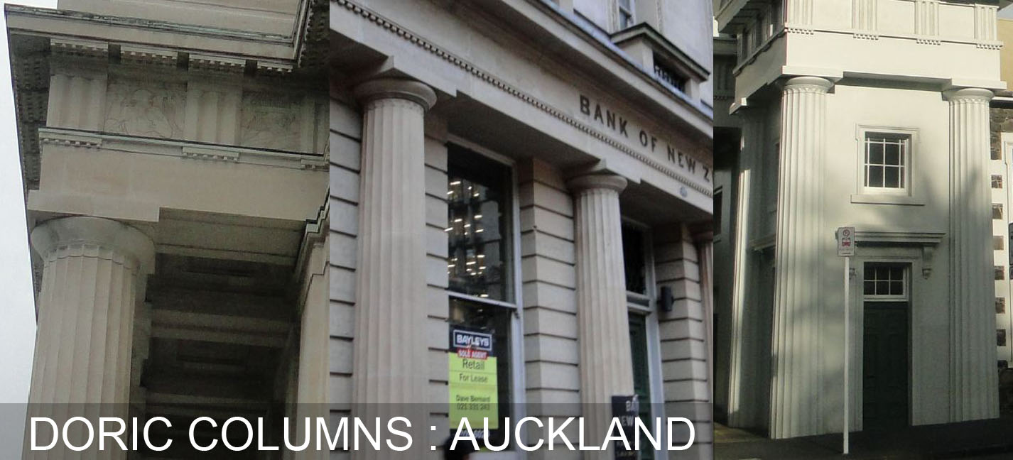
Doric is a Greek Order.  Sometimes people add a 6th order called Roman Doric.  It is similar to Tuscan, but has a fluted shaft.


The column that Marcello used to demonstrate his "scaling by spline" method had a smooth shaft so it was Tuscan.
It's an interesting example because it takes us to my second extract from the wiki-help.


Splines in Revit are not like Polylines in  Autocad.  You can't have arcs and straight-line segments.  It would be very nice if there was a "polyline" in Revit containing arcs & line segments that would scale up like a spline, simply by dragging the end point.  Then you really could make a Tuscan column that scales up at will.  As it is, the spline is a less-than-ideal tool for the purpose.  First of all there is a performance hit when using splines with many points.  Secondly you can only make a rough approximation to the curves of a tuscan column using a single spline.  Thirdly, solids based on splines have a nasty habit of looking decidedly wierd in elevation views.  Here are some columns I made based on Marcello's method.


There are 2 families here.  One just scales up.  The other has a Slenderness Ratio (SR) parameter allowing horizontal & vertical scaling to be separately adjusted.  They look pretty good in 3d, but not so hot in elevation.


We would expect to see horizontal lines expressing the mouldings.  These are missing because there are no clean angles, it's just one continuous spline curve.  Both families contain a single revolve.  In the simpler version, the spline starts & ends on the axis.  I managed to get quite close to the Tuscan profile, but you can see that there are no true right angles.  It's just one continuous curve.


In the other family the spline is associated with a second reference plane, a distance X from the axis.  X is defined as Height divided by Slenderness Ratio (X = H / SR)  This works quite well but the other problems remain.  I suspect that wikihelp is correct in encouraging us to keep splines relatively simple.


So let's try something much simpler, but still within the classical theme.

The image below is a simple drafting exercise.  Draw 3 straight lines plus 1 spline to form a closed loop.  Dimension the distance between top & bottom lines.  Copy everything to the right.  Select the top line and type in a new dimension.  The lines will stretch, but the spline will SCALE.  You can confirm this by copying the spline (thick line) and using the scale command to resize it.  Note that the normal connections between the ends of lines & splines are causing the the spline to scale when the line is moved


A second drafting exercise extends this technique to a classical moulding & shows how quickly a wide range of sizes can be generated.


But once again we have to use extra points to fake the straight lines & sharp corners.


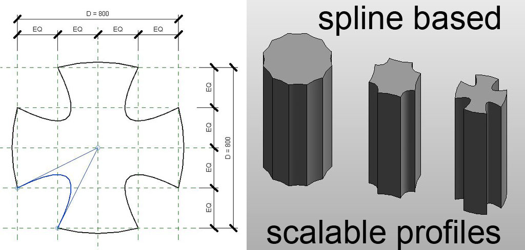
So I tried out a family that uses a combination of straight lines & a spline.  I'm using equalised dimensions to help control the scaling.  Width & Depth scale separately.  This is an important proof of concept because the spline is scaling diagonally across a grid of reference planes.


Now I have a profile family with 2 parameters: Width (W) and a slenderness factor (F)  Used in a sweep, this creates nice mouldings.


So I'm thinking that this is a more realistic approach to classical architecture with Revit.  Break it down into modular components.  Use splines where appropriate, keep them simple, scale by auto-stretch, use grids & equalisation.  Then it suddenly hits me that we could use this to make a doric profile, without resorting to conceptual massing.  Sure enough it works.


I experimented a bit more.  No doubt there are many variations on this method.  What if I had discovered this long ago ???  If I had known there was an easy way of making a scalable doric profile in vanilla Revit perhaps I would never have embarked on my pumpkin explorations.  Now there's a scary thought.


It's very easy to say "I love classical architecture" but do you love it enough to learn how it works before launching into a sloppy cut & paste version.  My brother-in-law Dave has this thing about authenticity, which he was applying to music & restaurants.  It's an elusive concept, but most of us apply judgements of this kind.  We talk about things being fake or plastic, use judgemental terms like "pastiche" & "pseudo".


Classical has never been my favourite style.  I always sided with Gothic, Arts & Craft, Gaudi, etc.  From around 1920 onwards, the most appropriate "style" for architecture has usually been the simplicity & abstraction of the modern movement.  I am not one of those pedants who label the use of past styles as "dishonesty".  Modernism has been around for about a hundred years (eg Fagus factory 1911) so why is it more honest to work in this style rather than say Art Nouveau, which is only slightly older ?


We all take inspiration from the past.  We utilise and adapt ideas developed by others.  In my view we are far too obsessed with the idea of "originality".  By striving to make every building "original", "unique" or "iconic" many modern cities have become a confusing mish-mash.  Personally I would not rule out any style or approach when designing a building.  The important thing is to have thought carefully about why you have chosen particular forms, materials, proportions.


So it is with the classical orders.  They have a very rich history and can be used in many different ways.  It is best to start by following "the rules".  Learn how to create balance, rhythm, proportion.  Once you have paid your dues, you can begin to improvise, reinterpret, develop a style of your own.  Generally speaking, people choose classicism because of it's associations with sophistication, tradition & good taste.  If you wade in thoughlessly you will simply achieve the opposite, like a parvenu who fakes an upper-class English accent.  It's easy to look ridiculous, hard to achieve the relaxed poise of authenticity.  For example I found the images below on this website while doing a web search for Tuscan Columns.


I've taken this detour in order to get back to the idea of scaling classical columns.  In order to decide how to do this in Revit we need to know what we are trying to achieve and why.  If you are looking for a quick & easy fix, architecture by numbers ... think again.  If you are willing to take the challenge of classical architecture seriously, then you will very quickly realise that creating 5 scalable families for the 5 orders will not take you very far.  It may be useful for quickly roughing out ideas, but that's all.  In a previous post I demonstrated how richly varied the Corinthian Capital has proved to be in practice.  You won't get far with a one-size-fits-all approach.  Tuscan may seem like a much simpler proposition, but if you were to photograph a couple of hundred examples from around the world, you would soon realise that simple scaling is not the answer.


At the very least you would want a slenderness ratio, square versions, round versions and pilasters (half columns)  Ideally you would be able to vary the base moulding, the relative height of the abacus, etc etc.  So I am back to thinking about the kind of modular approach I mentioned earlier.  I'm back in Dubai by now, recovering from a 24hr journey by playing with Revit in between bouts of snoozing.  I've managed a reasonable first crack at modular tuscan.


I don't have the energy for a full explanation of this family right now, but it makes some use of spline scaling, mostly for the shaft.  The base & capital are assembled from nested components.  I have to say that Marcello's method is much quicker & easier, but with the drawbacks mentioned above.  It all depends what you want to achieve.  For a quick study, the simple spline-scaling method will do the job.  As the design develops you will probably want to invest more time in developing a family that stands up to closer scrutiny.


That's all for now.  I will share some of these families when I've had a chance to clean them up a bit.  Also I want to tackle the same problem via conceptual massing.  I have a feeling that we can create square & round versions from the same family by lofting the form from nested profiles.  Watch this space.

PS Just to be clear, none of the above is intended in any way as a criticism of Marcello's work or methods.  He's a giant & I'm standing on his shoulders ... the view is spectacular :-)

Monday, May 6, 2013

BSL DOWNLOAD

It's seriously hot now, back in the UAE.  Total indoor life from now to September, with the month of Ramadan right in the middle.  England was sunny, but quite cool at times.  Made a nice change for me.


I am going to upload a PDF of the plan for my session at BIM Show Live.  Several people told me they enjoyed my more personal approach after lots of sessions on Data/Workflow/Change Management.  All these things are important of course, but my focus is on keeping BIM human, injecting that creative spark, looking for deeper meanings, did I mention having fun ?


I was so worried that I wouldn't finish that when I got to there, I had totally forgotten my concluding remarks.  It was supposed to go something like this:

Life is a journey. Mine has taken me to all kinds of interesting places: geographically, socially, intellectually. Visual thinking has played a central role in my life and the ancient tradition of drawing has been a constant source of inspiration.  I like to draw ... and in recent years BIM has become my favourite "pencil." 


BIM is not a radical break with the past. It’s an amazing tool, but no more radical than perspective or orthographic projection were in their day. When we read Shakespeare we don’t think, “if only he had a word processor, he could have done so much more”. It’s not what you’ve got, it’s the way that you use it.


I dream of the day when BIM is taken for granted. An everyday tool that is as natural to architects as a pencil, to engineers as a slide rule, to quantity surveyors as a spreadsheet.


The plan itself was "drawn" using Revit in "DTP mode".  In other words it's a drafting view that I used to organise words & images ... working out the structure of what I wanted to say.  There are 8 sections, each covering the same 3 topics.  The tradition of visual thinking, my lifelong love of drawing, how to "sketch" with BIM.


You can download it    HERE