This is quite ironic. I'm doing a pumpkin piece as a kind of diversion, an aside ... a pause to gather my breath before returning the the real business.
Can't even remember what set this off. And it wanders all over the place.

It starts with a globe & a 9 point adaptive component. It's a way to get a curved skin instead of the normal faceted, curtain panel look.

I want it to be scaleable, so the offset in the middle has to be related back to the width of the panel. Which means "reporting parameter". There is a very unhelpful message that sometimes pops up. It almost had me fooled that I was trying to do something impossible. Slowly the memory cells kicked in. You need to dimension to the ref planes, not the point itself. If only the message said that.

So what makes this different from my profile based pumpkins? The fact that I can vary the number of lobes. That's the benefit of the repeater/divided surface approach.

And now that the reporting parameter trick is working the curvature of the lobes is consistent, from pole to equater & back again.

The underlying "globe" is lofted from profiles. So we can make high-waisted versions, "squarish" versions etc.

Interestingly the number of lobes will reduce right down to 2, which is a bit odd. 3 is quite interesting though.

Inevitably I find myself growing mushrooms again.

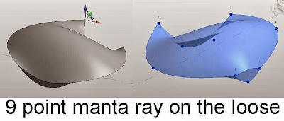
At this point I just placed a 9 point on the deck & played around with the points. It started to look like a manta ray and I thought about hanging one inside a box rig.
This didn't really work but it got me to thinking about shell roofs and Alfredo's excellent session at RTC Auckland.

Which brings me back to abstraction & simplification once more. I realised that Alfredo had simplified some of the forms for didactic purposes. I had been trying to create curved valleys and getting odd results. He had wisely kept the valleys straight. (Keep it simple - applies to everything, but especially teaching)

But how would you tackle a more accurate shell roof with curved valleys ? My first attempts produced a surface with an off-centre seam. Revit is looking for the nearest straight line, which in a hypar is always off at an angle somewhere. Orthogonal sections will always give you a curve. By the way, what a shame that we can't set a transparency for lines (over-ride graphics by element) I would have like my red arrows to be slightly transparent.

I took a break and made some saddle shapes. Just 3 curves hung on a cube rig. Select them and create form. Very simple and easy to flex.
Then it struck me that this could be a solution to my circular array if I just cut it with a void. The first version I made was symmetrical so you could only have even numbers of bays.

Took a while to get this working in a circular repeater. You have to link up the parameters and use a bit of trig so that the cut angle and the length of the nested family match up with the radius and number of segments in the host repeater family. Not too hard.

Then I rebuilt the family from scratch to make a single bay version. Simplified the construction slightly. It's easier to make the cut as a solid at first (so you can see it) and convert it to a void once you are happy.

Nest it up in the same way and we are in business

Put in a bit of work manipulating the parameters so that all the lengths are functions of the radius. Now you have a scalabel family with variable number of bays and controls over proportions.

Time to scatter a few around, explore the variants and set up a render.
I'm happy with that. A nice morning's work.

So back to pumpkins. What about using a similar approach ?

What I came up with is a variation on the box rig. Kind of a box with the corners cut off. Use it to hang profiles on. Pumpkins.

Not just surfaces, but solid pumpkins with a hollow centre
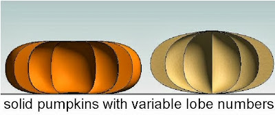
Oddly I managed to create self-intersecting geometry that didn't keel over and dime. Kind of a ghost pumpkin. Very weird.
It gets to me that sometimes you are trying to do something that seems perfectly achieveable and Revit just gives up. Then you attempt something really impossible and Revit goes ahead and makes it. All part of the fun I guess.

Finally I found myself making domes. Pumpkin domes. Garlic Domes. Domes with a wall thickness to them. AND very parameteric.

So I really couldn't resist making up a building for them.

Had to be a Russian style church/palace. Just a little fantasy.

So that was a weekend spent playing with pumpkins, more or less. First weekend in October to be precise,
Can't even remember what set this off. And it wanders all over the place.

It starts with a globe & a 9 point adaptive component. It's a way to get a curved skin instead of the normal faceted, curtain panel look.

I want it to be scaleable, so the offset in the middle has to be related back to the width of the panel. Which means "reporting parameter". There is a very unhelpful message that sometimes pops up. It almost had me fooled that I was trying to do something impossible. Slowly the memory cells kicked in. You need to dimension to the ref planes, not the point itself. If only the message said that.

So what makes this different from my profile based pumpkins? The fact that I can vary the number of lobes. That's the benefit of the repeater/divided surface approach.

And now that the reporting parameter trick is working the curvature of the lobes is consistent, from pole to equater & back again.

The underlying "globe" is lofted from profiles. So we can make high-waisted versions, "squarish" versions etc.

Interestingly the number of lobes will reduce right down to 2, which is a bit odd. 3 is quite interesting though.

Inevitably I find myself growing mushrooms again.

At this point I just placed a 9 point on the deck & played around with the points. It started to look like a manta ray and I thought about hanging one inside a box rig.

This didn't really work but it got me to thinking about shell roofs and Alfredo's excellent session at RTC Auckland.

Which brings me back to abstraction & simplification once more. I realised that Alfredo had simplified some of the forms for didactic purposes. I had been trying to create curved valleys and getting odd results. He had wisely kept the valleys straight. (Keep it simple - applies to everything, but especially teaching)

But how would you tackle a more accurate shell roof with curved valleys ? My first attempts produced a surface with an off-centre seam. Revit is looking for the nearest straight line, which in a hypar is always off at an angle somewhere. Orthogonal sections will always give you a curve. By the way, what a shame that we can't set a transparency for lines (over-ride graphics by element) I would have like my red arrows to be slightly transparent.

I took a break and made some saddle shapes. Just 3 curves hung on a cube rig. Select them and create form. Very simple and easy to flex.
Then it struck me that this could be a solution to my circular array if I just cut it with a void. The first version I made was symmetrical so you could only have even numbers of bays.

Took a while to get this working in a circular repeater. You have to link up the parameters and use a bit of trig so that the cut angle and the length of the nested family match up with the radius and number of segments in the host repeater family. Not too hard.

Then I rebuilt the family from scratch to make a single bay version. Simplified the construction slightly. It's easier to make the cut as a solid at first (so you can see it) and convert it to a void once you are happy.

Nest it up in the same way and we are in business

Put in a bit of work manipulating the parameters so that all the lengths are functions of the radius. Now you have a scalabel family with variable number of bays and controls over proportions.

Time to scatter a few around, explore the variants and set up a render.
I'm happy with that. A nice morning's work.

So back to pumpkins. What about using a similar approach ?

What I came up with is a variation on the box rig. Kind of a box with the corners cut off. Use it to hang profiles on. Pumpkins.

Not just surfaces, but solid pumpkins with a hollow centre

Oddly I managed to create self-intersecting geometry that didn't keel over and dime. Kind of a ghost pumpkin. Very weird.
It gets to me that sometimes you are trying to do something that seems perfectly achieveable and Revit just gives up. Then you attempt something really impossible and Revit goes ahead and makes it. All part of the fun I guess.

Finally I found myself making domes. Pumpkin domes. Garlic Domes. Domes with a wall thickness to them. AND very parameteric.

So I really couldn't resist making up a building for them.

Had to be a Russian style church/palace. Just a little fantasy.

So that was a weekend spent playing with pumpkins, more or less. First weekend in October to be precise,


