Pages

Sunday, September 25, 2011

STAMP COLLECTION

This is another post about my interactions with suppliers/manufacturers of building products.  Creative Concrete Concepts started out doing stamped concrete and have broadened out into a range of cement-based finishes.


They gave us a CPD recently and I asked my usual question (do you know about BIM & Revit) and got the usual answer (not really, but we're willing to learn)  So I've entered this dialogue where they send me jpegs and I demonstrate how these can be turned into Revit materials.


The plan is that this will generate the enthusiasm for them to take ownership of the project and make their entire range available in Revit format.  This opens up a discussion about how best to present materials as a downloadable package, complete with image/bump map pairs, suitably scaled fill patterns, specification codes etc.


But first of all, lets make a material. The source image should avoid these common mistakes:
  • Image zoomed in to a small area, can't find the repeat
  • Taken from an oblique angle, distorts when you correct the perspective
  • Uneven brightness: dark on the left, pale on the right.
Step 1: crop the image to a rectangle that will repeat.


Step 2: offset the images so that the corners move to the middle
Step 3: make small adjustments to eliminate the cross-hairs effect
Step 4: save the image at an appropriate size


Step 5: change mode to grayscale
Step 6: enhance contrast
Step 7: save as bump map


Using this process you can create pairs of images for each material type.  These will be used in the render definition, which is one of 4 tabs in the material dialogue. 


The "Graphics" tab sets appearances used in construction drawings:  surface appearance and cross-section hatch.  The cut-pattern can be one of the standard drafting patterns supplied with Revit.  The surface appearance needs to be a model pattern.  This could be a "pat" file  downloaded from the web, or you could use a programme to generate your own hatch.


For our office I have compiled a "collection" file of fill patterns which is available on the server. This grows with each new project and encourages basic naming standards for filled regions & fill patterns. 
The last 2 tabs contain non-visual data (sometimes called the "I" in BIM)  This is information that can be picked up in tags & schedules.  Keynotes are potentially a very powerful feature because they provide the link to Specifications.  We us the British NBS system, which I still prefer to the US Masterformat, but that's another post.  Stamped concrete is going to come under section M10 and you will need to create some custom clauses here for the different patterns used on your project, perhaps M10/170A Proprietary Stamped Concrete Screed: type A, where type refers to the mould pattern and colour.


Revit will be able to calculate areas for type A, type B, type C ... and schedule this out with whatever information you type into the material properties.


Now won't it be nice when every brick manufacturer hands out Revit materials for their entire range with all this information already embedded. Not to mention tiles, rainscreen cladding, cultured stone, terrazzo, formica ...  So I'm making the effort to get this message across to every supplier I meet, and if you all do the same.  Surely it's achievable.

ANYONE FOR BIMICAD ?

On Thursday afternoon I attended a "BIM Seminar" which had found its way into my inbox.  From the agenda I had assumed this was to be a cross-platform discussion of BIM issues, which seemed to me a most refreshing idea.

In reality it turned out to be a sales pitch for ArchiCAD.  I don't regret attending.  It's a few years now since I used ArchiCAD and it was interesting to see how it has developed.  There was also a session on VICO, software that has much in common with the likes of Navis Works, allowing construction managers to access the information in BIM models to drive their programming & critical path analyses.


It was a little strange though.  Couldn't help feeling there was an attempt to hijack the term BIM. 

Probably the highlight of the afternoon was the BIM explorer, an iPad app which allows clients & others to walk around exported Archicad models through a very simple interface.  But again, why BIMx ?  Do they intend to supply plug-ins for Revit and Bentley Architect, or is it really better called Archi-View.  Not quite as cool, but perhaps more honest.


Personally I think Graphisoft are doing some interesting things and I'm glad that Revit isn't the only game in town.  I would also like to see real BIM seminars taking place where ordinary architects, contractors, clients etc can discuss the implications of the changes we are facing as an industry, regardless of the proprietary software we have chosen.

What are the legal implications of handing over a digital model to the contractor ?  If he cuts his own section at an arbitrary point through our model and finds that the full intricacies of the way materials join together is not captured in 3d, can he make a claim ?  Or are we stuck forever in a world where the 2d paper prints (stamped & signed) are the only truly legal records of our design ?

Tuesday, September 20, 2011

IMAGE MANIPULATION


Mental Ray renders are great, but sometimes you want something softer, more impressionistic.  There are many ways of achieving this, but ideally I want to stay as close to the Revit workflow as I can. So I aim to limit any image manipulation outside of Revit to what I can achieve in 10-15 minutes.
You can see some examples on my "Revit work at GAJ" page


I usually start be combining a shaded or hidden line image with a render.  Make sure they are both the same resolution, then it's just a simple ctrl-A, ctrl-C, ctrl-V to get one layered on top of the other.
Next step is to duplicate the background, apply a watercolour filter and fade this new layer to say 40% transparency


Finally, duplicate the hidden-line layer, and set the mode to overlay.  Add a layer mask, and make the centre of the mask partly transparent by applying black with a big soft brush set to say 10% opacity. You are looking to create a mask that fades from dark grey in the middle to white at the edges, basically a big soft oval vignette.  This creates a subtle fading towards the edges.


With practice you can create very nice images in less than 10 minutes.  For best results you need to fine tune the transparencies and final image contrast levels to suit that particular image.


Some more examples below, including a "squiggled" DWG export overlaid on a live Revit view.


Combining rendered views with hand sketching can be very effective.  This one was done to communicate our comments to a specialist rendering service employed by the client.


Have also experimented with Autodesk Impression.  It's a free download, but you have to do a DWG export first, so the workflow gets a bit too elaborate for regular use.


One last thought. Wouldn't it be great if this kind of image could be produced internally in Revit.  Some kind of plug-in maybe that allows you to combine a hidden line view with a render and set the transparency. I suspect it's beyond the capabilities of the API at the moment, but it would be very nice if you didn't have to leave Revit, create a jpeg, delete the old one from the sheet then position the new one carefully in the same place.

see this post   Ronchy Images  for more on image processing.

Sunday, September 18, 2011

BEAM ME UP SCOTTY


Scott Jezzard is a young Australian architect who I introduced to Revit 4 years ago. He left GAJ a few months ago and has been doing some very impressive freelance Interior Design work.


He's the kind of guy who always wants to stretch Revit to its limits (and beyond)  He also has a background in fine art and sculpture, which shows in the modelling of some of the furniture families he custom-built for these renders.


The first 3 shots were modelled and rendered entirely in Revit. The care he took to get the materials and lighting right has really paid dividends. 


One nice touch is the bump map/cutout associated with the Rug decal.  Not something you're going to use all the time, but a very nice feature when you need it.  If you've never experimented with this aspect of decals, give it a go, can be very effective.


If you want to go further than this with soft furnishings, you will have to export to 3d Max, which is exactly what Scott did for the next group of renders.  Autodesk have an excellent workflow for this based on the FBX file format.  It was Scott's first time to use this, but the results are excellent.
Max has a much more sophisticated set of modelling tools for tackling thinks like soft furnishings and buttoned leather. Also more controls for material definition and lighting effects. But its a complex program, so you need to be prepared to put in the time to learn its secrets. 


The simplest solution for medium sized firms is to do most of your rendering in Revit, but have a couple of hotshot Max guys to handle the top end renders, particularly interiors with soft furnishings and rich materials.


A couple of screenshots from within Family Editor to close out this post, just to give a little insight into the use of swept blends and void cuts.  Nice work in my opinion.


Scott is currently weighing up his options, and open to job offers in either Dubai or Australia, so if anyone out there is interested, let me know and I'll put you in touch.  Buy now while stocks last :}

Thursday, September 15, 2011

FIRST PRINCIPAL

Last night we were at the Middle East Architect awards ceremony, held on the Palm Jumeirah, which is a short taxi ride from our offices.  We had entered several categories and came away with 4 second places plus one outright winner. 


Appropriately it was our boss, Brian Johnson who won : Principal of the Year 2011, in recognition of 30 years of outstanding work in the Region, including one of Dubai's first iconic buildings, the Creek Golf Club, which features on the 20 Dirham note.  Not so many architectural practices who can hand out bank notes as business cards :)

This year there was a new category: BIM Project of the Year, and I am proud to say that we earned a "Highly Commended" second place for the work my Revit team has done on Saray Bandar Jissah in Oman.  A big thank you for all the guys & gals on the team for all the effort they have put in over the past year on this challenging project.


This is a residential resort with about 350 villas, a short drive from Muscat .  Advanced earthworks are due to start later this year.  The setting is quite dramatic with jagged mountain ridges and valleys leading to an unspoilt beach on the India Ocean.  Our Revit work ranged from Strategic Masterplanning to meticulous detailing of bathroom layouts. 


We have a complex set of cross-linked and nested files in order to handle the complexity of the site within our hardware constraints.  All the villas have 2 versions: the full villa with all the CD sheets and a simplified massing model, sufficient for most masterplanning exercises.  We swop these links in and out as needed.  There is a file for the overall topography, with holes cut in it for each group of villas.  Typically we have 10 or 12 villas in each zone file, where we model all the platform levels, the cut and fill, the landscaping, streel lights etc.


The infrastructure engineers issue their drawings in separate packages arranged by sub-discipline.  The Revit model has really helped us to see how the earthworks, surface drainage, retaining walls, etc fit together in 3 dimensions.  In many cases of course they don't fit together, and very rarely do they take into account the architectural and landscape design requirements, partly because their work had to be completed far in advance of ours, so they are always trying to finalise things before we have been able to develop our designs properly. 


Conversely the landscape designers are a couple of steps behind us and often only have 2 dimensional concept sketches, when we really need to finalise ground shaping levels with the engineers.  Our masterplanning model has been a fantastic tool for highlighting critical issues that need to be resolved and obtaining sign-off of the decisions that matter so that the engineers can complete their tender package and the landscape guys know the parameters whithin which they will have to work when they move to detailed design.


At a smaller scale we have had to develop a strategy that allows a mass concrete marine wall to be built 2 years in advance to a pool specialist coming on site to construct infinity edge pools that overlook a salt-water lagoon.  Once again it was essential to be able to visualise relationships between different elements owned by multiple stakeholders in the design team, and to think about sequences of operations.  Revit has a great ability to duplicate views and hide elements so that you can simulate a construction sequence.  The section box views are also crucial to this kind of coordination exercise.


For the bathrooms I went onto the Duravit & Hansgrohe sites to download 3d CAD models of the selected fittings and incorporated these into Revit families.  Often these familes contain 3 or 4 nested components pre-configured into their correct relationships (toilet pan, TRH, push plate, hand spray, cistern boxing)  If the relationships change,  the families can be reloaded into the 50 or so bathroom types in the project to maintian consistency with very little effort.  This is where the the "revise instantly" origin of the Revit name is vindicated.


Kitchens were done to similar level of detail, and our client put us through 3 or 4 design iterations, all presented in cutaway perspective views as well as traditional plans & elevations for each of the dozen or so kitchen types.


I'll try to do a more detailed post on some of the families we developed for this project soon, but to conclude here's a rendering of one of the villas done directly from the Revit model


Monday, September 12, 2011

THE WINTER OF REVIT CONTENT

Apologies to Shakespeare, but we are heading for winter (good news here in the UAE) and Revit Content does seem to be popping up all over the place these days.

It took a long time for manufacturers to wake up to the world of BIM, and some of the content is barely useable, but the important thing is that the wheels are starting to turn.  More and more people are getting involved, arguments are erupting over naming standards.  The hive is buzzing away.

For example take a look at this site: REVIT WORKS


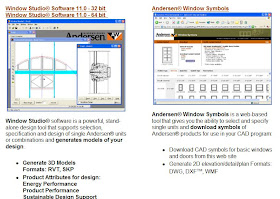
New Zealand based content providers who are churning out some excellent stuff.  Will be interesting to see the "Door Factory" which takes more of an ArchiCAD style approach to making doors via a series of carefully designed dialogues.  Andersen have adapted their Window Studio software to work in a similar manner as a Revit plug-in that generates door & window families.  This is a good first attempt and a big time saver if you are specifying from their very extensive range, but the resulting families are not parametric in any way. 

It will be interesting to see how this evolves with feedback from end users.     


We had a CPD from the local Zumtobel team not long ago and as usual I quizzed them about getting their lights in Revit format.  They promised to get in touch with the head office in Austria, and sure enought about 6 weeks later I go this link  ZUMTOBEL LIGHT FAMILIES


They appear to be perfectly useable families too.  Only a fraction of their full product range but if you check the dates, they haven't been doing this very long yet.  Will be interesting to see how it develops.


Don't know if you noticed but we've been to NZ, US & Austria.  So this is an interesting global network building up.  David Light posted a link to more NZ content the other day.  Plumbing Fittings what is more !  Not many decent Revit toilet families around yet, as I have mentioned before.  Previous Post 

Turns out there is a whole bunch of interesting content on this site.  Well worth keeping a regular eye on.  Seems to be a very pro-active Revit community down there in NZ.  Product Spec NZ


 I met Tim Bates from Newforma this week and it was interesting that he cited Content as one of the big issues in the BIM world at present, not just availability, but also standards setting and how to manage all that information as it grows.  Let's face it there's going to be an enormous amount of stuff out there once Manufacturers really start pumping out there entire product line.  Type catalogues are all very well, but there has to be a better way of selecting what you want from thousands of options and of keeping your content up to date too.  Will Revit libraries get constant upgrade warnings when product ranges change ?   At present I am downloading anything I can get my hands on and putting it into "Collections" files, just to make it accessible to my Revit users.


Lots of this is stuff we create ourselves of course, but a fair amount comes from the web, some of it tweaked to work better.  Once we start getting really good stuff from the manufacturers though, either they go the Andersen plug-in type of route with automatic upgrades when new content arrives, or they have really good download sites.  And these are rare. Usually you spend far too much time navigating backwards and forwards trying to understand what is available, then remembering the name of the range you want, and selecting CAD items to put in a cart, only to have to unzip them all at the other end and arrange them into folders so you can remember later on what those cryptic file names mean.

So I can't wait to see what the NBS guys come up with.  We use the NBS on-line system for all our specifications and I just think it's so well written and presented.  So I was excited to hear about the new National BIM Library that will come on line in November.

Winter of Revit Content indeed.

NBS BIM library


Monday, September 5, 2011

REFERENCE PLANE HEAVEN

I came across the term "reference plane hell" in a forum a couple of years back and it's always stuck in my mind.  Some guy who was probably used to the simplicity & freedom of Sketchup was struggling to do things the Revit way. Most of us have been through this frustration and many regular Revit users never quite figure out how to unleash the power of reference planes.


I decided to make a deck chair family the other day, and very quickly realised this is a  classic reference plane situation.  I started off by making a "typical member" which is a simple rectangular extrusion.


Four of these get put together to make one of the frames.  So nest the "typical member" into a new family, set up your reference planes, place 4 members and constrain them.  By associating the length of members with the Width & Length of the host family your frame becomes parametric and ready for nesting into the Deck Chair family itself.


This third family is where the reference planes really start working for a living.  Go to a side elevation and draw angled planes.  Give them names (important step)


Load a frame and place it on the work plane for the sloping back.  User created workplanes only show up if you have given them names.  This frame family is now locked into a relationship with that reference plane and will remain parallel to it.  You can go into the front elevation and align it centre-to-centre.  Lock it in place if you like.  Nudge it up and down, it will simply slide along the plane.  If you want it to move away from the plane you will need to specify an offset in the properties dialogue.


Go ahead and place the seat on it's own reference plane.  The 2 struts and the rail are placed on the third work plane and have different breadth & depth parameters. This gives the illusion that the rail is rotated through 90 degrees.  If you need to adjust the angles of the frames, just go into a side view and rotate the reference planes. 

Once you understand the way reference planes work it's easy to control the geometry.  But if you just place objects without linking them to planes, trying to rotate them in 3 dimensional space is very frustrating.


The rest is quite easy: an extrusion for the canvas, some material parameters and you have a perfectly acceptable deck chair to populate the pool decks of your resort projects. 

Just to recap, the deck chair has two nested families, a strut and a frame.  Each of these nested families has two types, with slightly differen sizes.


Struts are also nested inside the frame family, but I renamed the family as "member" and there is just one type, named "typical".


If you fight against Reference Planes, then life can be hell, but if you learn to work with them, and plan your families systematically, Reference Planes will actually give you greater freedom and control than the simplistic, push-pull methods of a programme like Sketchup.  No offence to Sketchup, it's a great little app, but Revit can take you higher  ...  if you have the patience to learn its heavenly secrets.