STILL LEARNING AFTER ALL THESE YEARS
Soane's Bank of England is familiar territory to me by now. It's been a while since I discovered a drawing for a new space that I hadn't noticed before. Used to be something that happened regularly, but after 2 1/2 years I have come to know both the building and the drawings archive pretty well. So I got a bit of a thrill when I realised what this drawing was really about.

I had assumed it was an early study for the Discount Office, which is strange because it clearly says that it is the lobby leading to that office. As soon as the penny drops it relates very clearly to a space on the floor plan (although the door to the Silver Room is puzzling). I'm quite excited, because it's an interesting space, and fills out the sequence of rooms that I have been working on recently.
The treatment is very similar to the waiting room corridor, with rusticated walls and Ionic columns, plus yet another skylight, above a vaulted ceiling. There is a second drawing with orthographic views. I'm looking forward to developing this, maybe next weekend.

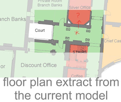
Here is a model view of the lobby, showing the route from the Long Passage leading to the Discount Office entrance door. The new skylight position is marked by an asterisk, and the large arched window into the Discount Office is awaiting glass and framing.

I started on the Discount Office itself towards the end of this weekend: mostly developing the coffered ceilings. I roughed out the space at least a year ago, lots of arches and Soane's usual division of the space into a central hall with side and end aisles.

More discoveries this weekend. For some time now, the linked models have not been showing up in the A360 viewer. I decided to try removing them and re-inserting; a successful strategy in the end.

Along the way I thought I should record the positions of the links using shared coordinates before removing them. Turns out that you can't "Publish" coordinates in A360. I guess it has something to do with the models not residing locally so more chance of corruption when the system tries to write to it. In my confusion I pressed "reconcile" a few times, thinking this was an equivalent process, but of course it is actually acquiring coordinates from the link. Essentially True North was reset back to Project North,

This in turn prompted me to look once again at the orientation of True North. I was looking to display a grid in Google Maps and came across a link to a Caving Society which has done this via the API. Actually I have a plan view with lots of different maps brought in, some historic.

Cross-checking these and taking readouts of coordinates from Google Earth at the four corners of the site convinced me that to change the angle between True & Project North from 24.5 to 26 degrees. Not sure that it matters very much for the work I am doing, but it was an absorbing puzzle.
I ought to mention that the A360 viewer is much improved now that they added edges. It's quite responsive too, given the size and complexity of this model. Here's a shot looking from the Residence Court towards Lothbury Court, not a bad place to live if you were the Secretary or Chief Cashier.

The first half of the weekend was more straightforward, but also rewarding. I was increasing the level of detail on the Governor & Deputy Governor's Rooms. Don't have time to describe the process right now, but a couple of Enscape images will convey the reults. Deputy Governor's office is all about subtle division of space to define a "corridor zone" at one end, leaving the main space centred on the fireplace with a circular recess in the ceiling. Had fun with the decorative frieze at the junction of wall and ceiling.

The Governor's Room is a blend between Taylor & Soane. I had to increase the pitch of the groin vault to match archive drawings, then it was mostly down to carefully adjusting the wall panels ... plus a bit of fun with a repeating dentil family topping off the corner recesses. I think Soane inherited the groin vault and high level windows from Taylor, but the window into the Waiting Room Court is definitely his. I suspect most of the decorative detail is of his devising also, but it's hard to be sure.

LINKS to 360 panoramas of these two spaces:
Governor - panorama.enscape3d
Deputy - panorama.enscape3d
The Soane drawings I began with are of course copyright the Soane Museum and downloaded from their online archive which you can access here.
http://collections.soane.org/home
SUMMARY
I'm going to try out a suggestion I received recently from Dmitry and summarise the main points arising in this post. I have set myself a rambling, diary style format for my posts, bordering on "stream-of-consciousness" I don't want to abandon this, but a summary at the end seems like a good idea.
Soane's Bank of England is familiar territory to me by now. It's been a while since I discovered a drawing for a new space that I hadn't noticed before. Used to be something that happened regularly, but after 2 1/2 years I have come to know both the building and the drawings archive pretty well. So I got a bit of a thrill when I realised what this drawing was really about.

I had assumed it was an early study for the Discount Office, which is strange because it clearly says that it is the lobby leading to that office. As soon as the penny drops it relates very clearly to a space on the floor plan (although the door to the Silver Room is puzzling). I'm quite excited, because it's an interesting space, and fills out the sequence of rooms that I have been working on recently.

The treatment is very similar to the waiting room corridor, with rusticated walls and Ionic columns, plus yet another skylight, above a vaulted ceiling. There is a second drawing with orthographic views. I'm looking forward to developing this, maybe next weekend.

Here is a model view of the lobby, showing the route from the Long Passage leading to the Discount Office entrance door. The new skylight position is marked by an asterisk, and the large arched window into the Discount Office is awaiting glass and framing.

I started on the Discount Office itself towards the end of this weekend: mostly developing the coffered ceilings. I roughed out the space at least a year ago, lots of arches and Soane's usual division of the space into a central hall with side and end aisles.

More discoveries this weekend. For some time now, the linked models have not been showing up in the A360 viewer. I decided to try removing them and re-inserting; a successful strategy in the end.

Along the way I thought I should record the positions of the links using shared coordinates before removing them. Turns out that you can't "Publish" coordinates in A360. I guess it has something to do with the models not residing locally so more chance of corruption when the system tries to write to it. In my confusion I pressed "reconcile" a few times, thinking this was an equivalent process, but of course it is actually acquiring coordinates from the link. Essentially True North was reset back to Project North,

This in turn prompted me to look once again at the orientation of True North. I was looking to display a grid in Google Maps and came across a link to a Caving Society which has done this via the API. Actually I have a plan view with lots of different maps brought in, some historic.

Cross-checking these and taking readouts of coordinates from Google Earth at the four corners of the site convinced me that to change the angle between True & Project North from 24.5 to 26 degrees. Not sure that it matters very much for the work I am doing, but it was an absorbing puzzle.
I ought to mention that the A360 viewer is much improved now that they added edges. It's quite responsive too, given the size and complexity of this model. Here's a shot looking from the Residence Court towards Lothbury Court, not a bad place to live if you were the Secretary or Chief Cashier.

The first half of the weekend was more straightforward, but also rewarding. I was increasing the level of detail on the Governor & Deputy Governor's Rooms. Don't have time to describe the process right now, but a couple of Enscape images will convey the reults. Deputy Governor's office is all about subtle division of space to define a "corridor zone" at one end, leaving the main space centred on the fireplace with a circular recess in the ceiling. Had fun with the decorative frieze at the junction of wall and ceiling.

The Governor's Room is a blend between Taylor & Soane. I had to increase the pitch of the groin vault to match archive drawings, then it was mostly down to carefully adjusting the wall panels ... plus a bit of fun with a repeating dentil family topping off the corner recesses. I think Soane inherited the groin vault and high level windows from Taylor, but the window into the Waiting Room Court is definitely his. I suspect most of the decorative detail is of his devising also, but it's hard to be sure.

Governor - panorama.enscape3d
Deputy - panorama.enscape3d
The Soane drawings I began with are of course copyright the Soane Museum and downloaded from their online archive which you can access here.
http://collections.soane.org/home
SUMMARY
I'm going to try out a suggestion I received recently from Dmitry and summarise the main points arising in this post. I have set myself a rambling, diary style format for my posts, bordering on "stream-of-consciousness" I don't want to abandon this, but a summary at the end seems like a good idea.
- Always be ready to find something new in old/familiar material
- Soane's variations on a theme are a wonder to behold
- The BIM360 viewer is much better with the black edges showing
- Design Review & Navis could benefit from this IMO
- Can't "Publish" shared coordinates in C4R, only "Acquire". Plan carefully
- Would be great to have a couple more collaborators on Project Soane