Tuesday, March 31, 2020

WEB WEAVING - RE-LIVING 2012


Second pass at the Revit -Excel-Revit workflow that I had picked up at my first Revit Technology Conference. 


This is quite a funky post really… Starts with a step-by-step “how to do it” then inserts an image that combines digital drawing with a bit of photoshop colouring.  I must have been very optimistic about the Wacom Inkling at that stage I think (August 2012) Sadly it didn’t catch on really.


Then I inserted a GIF.  Which was quite a bold move for me at the time.  I think I should try to do more GIFs really, (not to mention YouTube clips) 


https://grevity.blogspot.com/2012/08/excel-yourself.html


The next post is more of the same really.  Seemed very exciting at the time, but my interest in clever jiggery pokery has declined I think.  Technical tricks are not an end in themselves for me.  I want to just have a tool that I get very familiar with, then focus my attention on what I want to achieve without much thought about technique.  That should be handled at a subconscious level.  Like riding a bicycle or swimming perhaps.  You want to have a good technique, but you don’t want to be thinking about it all the time
.

And another GIF in there.  My fad for late 2012.


https://grevity.blogspot.com/2012/08/slipping-sliding.html


I like the next one.  One of my earliest attempts to capture the feel of organic building materials. Parametric “not quite circular” huts, featuring wiggly poles.


I really should come back to this and see how far I can take it.  In many ways it showcases the difference between a “way we build” study and a commercial building project.  Not much demand for representing this kind of technology in “day job BIM” … but if you are interested in exploring and discussing vernacular building styles around the world … that’s when the “BIM pencil” approach comes into its own.


https://grevity.blogspot.com/2012/08/still-on-excel-theme-but-taking-new.html


And back to the random Revit-Excel-Revit explorations.  Various different curtain panel families, devised to showcase a variety of possible effects.  I think this kind of work has been overtaken by the abilities of dynamoBIM with many reviteers around the world acquiring the ability to control complex façade designs in a controlled way.


https://grevity.blogspot.com/2012/08/square-dance.html


I think I must have seen a design for an art work and decided that this would be a good candidate for another randomising study.  So this is now a customised Generic Model with a nested array of rectangular elements.  


Another GIF in there as well. 


https://grevity.blogspot.com/2012/08/organ-grinder.html


I’d forgotten about the next one.  The Building Design Suite has been with us for a long time.  This was a weekend spent trying to persuade myself to get more value from the other software in that package.  Looking back almost 8 years later, very little of that actually panned out for me.  That’s an interesting expression, “panned out” does that come from Gold panning? How does our brain figure out the meaning of terms like that?  Doesn’t seem to require understanding the derivation. 


The comments on 3dMax trees and Showcase as a viewer are fascinating.  A deeply felt need that was finally fulfilled by Enscape3d, several frustrating years later.  And the Navis timeline feature.  I really thought I would find time to use that in my “Way We Build” work to animate simple bricklaying processes that I used in my 20s on building sites. 


https://grevity.blogspot.com/2012/08/sweet-talk.html


Aha!  This one was inspired by a post by Zach Kron on his Buildz blog.  What an inspiration that was for so many people (the blog).  He made a version of the Pantheon coffer dome using Revit 2010.  I think that was the first incarnation of “Point World”.  My post was done about 3 years after Zach’s though.


https://grevity.blogspot.com/2012/09/cough-cough.html


And another follow-up to Zach’s work.  I think I must have been making a conscious effort to go back to stuff that had gone way over my head at the time.  The spiky slug with random height pyramids was just one of those things that came together instinctively and proved exceptionally “photogenic.”  I’m still quite proud of that.  


The images produced by combining renders with shaded views in Photoshop had become standard fare for me.  I could rattle those off in no time.  Somewhat overtaken by slightly different processing methods using Enscape3d renders as a source.  I still like to soften renders and use my subconscious judgement to capture the mood I want.  Not always, but quite often. 


https://grevity.blogspot.com/2012/09/slug-it-out_6.html


Which takes us to another theme that gripped me for a while.  Musharabiya screens in Point World.  Quite a fertile area.  Somewhat labour intensive creating the curtain panel families but once made, adaptable to many different shapes of surface. 


https://grevity.blogspot.com/2012/09/screen-dump.html


I have a folder on my hard drive somewhere (actually I know exactly where it is and it syncs to the cloud so has something approaching eternal life) that is full of Islamic patterns.  Not all of these work well with “Curtain Panel by Pattern” but I spent a few weekends plodding through a few that caught my fancy … mostly fairly simple. 


https://grevity.blogspot.com/2012/09/patternising-with-natives.html


It’s interesting to note that all these tessellation exercises began with an analysis using 2d drafting in Revit.  That was a way of understanding the essence of the pattern, and deriving the Normalised Curve Parameters necessary to make it work in an adaptive setting. 


I’m pretty sure that the guys who came up with the conceptual massing environment (Point World) didn’t anticipate it being used for musharabiya patterns, maybe I’m wrong.  I have made use of this in my day job, several times.  Always a bonus.


https://grevity.blogspot.com/2012/09/more-web-weaving.html


And back to the Wacom Inkling.  This could be one of the best examples of putting it to use, and a rare example of putting the cartooning skills of my use to work again.  


I was trying to make the point that it’s easy to criticise the work of others from your “virtual armchair”  I’ve never been an out-and-out Autodesk fan-boy, but the factory basing mentality always rings hollow to me.  I really should do more sketching in this mode, now that I have Sketchbook Pro on phone and tablet.  (Note to ageing self)


https://grevity.blogspot.com/2012/09/factory-bashing.html


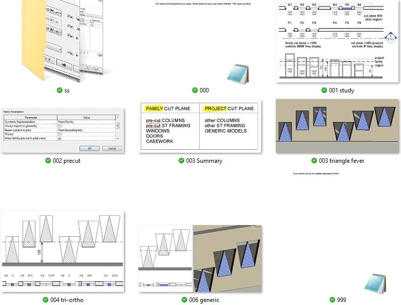
And here comes a rarity.    A deep dive into sparsely documented Revit functionality.  How do cut planes within Family Editor interact with Project cut planes?  Depends on the family category of course and it took me a while to figure out.  Most of the time this stuff just works, but once in a while you have a situation where you need to know the rules of the game.


https://grevity.blogspot.com/2012/09/fanlight-fanny.html


So the last one in this series is a continuation of the same investigation.  It seems I had stumbled into an area where very few had knowingly trod before. 

Next recap post will cover my second pumpkin adventure, which seems so long ago now, but it sure was fun.


https://grevity.blogspot.com/2012/10/cut-cut-cut.html


Saturday, March 28, 2020

OFF THE GRID


For some reason I started watching YouTube videos of Notre Dame again.  I came across one (in French) that deals with renovation activities from six or seven years ago.  There is a great sequence that shows the casting of a set of new bells.  It also deals with improvements to the organ, including the new console which Ryan did such a good job of modelling.


https://www.youtube.com/watch?v=Sw6Q8cuWn1Q&t=972s


I started to notice fleeting glimpses of areas that have intrigued me, so I kept hitting the pause button and taking screen shots.  There are steps where the aisles of the choir hit the curve of the apse.  It’s very difficult to get a clear view, because the flying buttresses get in the way.   I was aware of this step, but I hadn’t realized that it contained little rows of windows.  Something similar happens along the nave, but at a higher level.  That was a mystery at first until we realized that the clerestory windows had been enlarged at a later date.  Maybe the step in level where the choir meets the apse tells a similar story.


The next one was really exciting to me.  Some guys are threading a big flexible pipe out of one door and into another.  This is at the NW corner of the transepts.  I’ve been looking for a view of this area for a few weeks now, to confirm my idea that the door above the short flight of triangular steps leads to the bridge across the North transept, (below the rose window) by going outside and back in again. 
 1 = the door at the top of the steps.  
 2 = a small door I was unaware of that seems to lead into a square “chimney” which remains somewhat mysterious to me.  
 3 = the door leading to the bridge, and
 4 = an arch that seems to be propping up that chimney.  This is also completely new and unexpected to me, even though I’ve been working on this model for almost a year.


So there are some changes here that need to be made when time permits.  The arch is fairly straightforward.  (1) but the roof needs to be raised and converted into the “flat-stone-slab” type.  I’m not quite sure how that works and what the knock-on effects are for the windows below and the vaults over the chapels, which relate to the windows on one side and to arches into the outer aisle on the other side.  I had assumed that you would have to go down some steps to get to the roof surface and back up again to access the door to the bridge.  An interesting puzzle to tackle there.


So what about the title?  The literal meaning refers to the distortions in the floor plan.  Could we actually reflect this in our Revit model?  A bit of drafting to explore this.  Looking at floor plans, sometimes they have been straightened up.  Sometimes they seem to bent at the crossing, like a broken backbone.  Lying in bed one night I got the idea of creating the choir as a separate link and rotating the whole link by a degree or two.  But it doesn’t work.  The distortions are more complex than that.  


I drafted out a skewed grid that seems to work quite well.  But decided against trying to implement it.  It’s still a simplification of reality, so we might as well use a simplification that makes modelling a lot easier (an orthogonal grid)


Another thing I’ve been doing while lying in bed is to practice inventing ornament (leaves and scrolls) by drawing on my phone.  I was inspired by some YouTube videos that I watched, but rather than copy something, I just adopted the general idea and improvised.


Back to vaults. The sexapartite (sexa/hexa whatever) vaults that I made long back are a bit of a mess.  I have a much better cross vault family based on spherical geometry, so I can use this for the man span.  Then I can construct the two side arches, plus the big arch across the middle.  Took a while to figure out the geometry and convert it into formulas, but I got there


That’s as far as I could get with the traditional family editor.  The side vaults are kind of like the zigzag vaults around the apse.  So I decided to use the 9 point adaptives that I had used there.  


That worked fairly well, but I had to repeat the same sequence 8 times, and they tend to click onto the wrong edge … because the ribs have lots of parallel edges.  But at least you end up with a family that adapts to different widths and depths


That as long as it remains regular.  Ie the two side arches have to be the same size and everything must be orthogonal. That won’t work for the transepts because the aisles to the west are different widths compared to the ones on the east side.  Basically, we need to “fake” the skewed grid in some way.  My solution (for now) is to rotate the centre rib slightly.  So I have a second version of the family that handles the transition across the transepts caused be the different aisle widths.  It’s a cheat of course, but it works quite well.


While I was working on this, Nader popped up on Slack talking about a book by Andrew Tallon that he had acquired.  He’s the guy who scanned the cathedral about 12 years ago.  He was a Belgian/ American academic who died somewhat tragically in 2018 and scanned many gothic cathedrals.

In this book there is a colour coded diagram that indicates when different parts of Notre Dame was built.  I think this must have been created by a graphic artist because, although it picks up the skewed grid quite well, other aspects of the drawing are quite inaccurate.  It’s fine for the purpose intended though.  It’s quite interesting to compare it to a much older drawing that I found on the internet when I first started working on Notre Dame.


More interesting are some images taken from the point cloud.  At the moment I only have some slightly distorted images taken with a smart phone, but they still provide useful insights. 


It’s quite interesting to reflect on the various activities that combine to form the experience of Project Notre Dame.  There are days of intense modeling activity.  Periods of sifting through source material and comparing it to the model.  Times when the information coming in seems to undermine all the progress to date.  Weekends when I can’t resist going off at a tangent.  


The cumulative effect is a very rich tapestry of background familiarity.  Looking at new photos I quickly realise just where I am in the building and what I expect to see.  New insights pop out from the background and tap me on the shoulder ... "hey look, you didn't notice me before!"


Friday, March 20, 2020

TURNING THE CORNER


A couple of weeks ago I took a close look at the four corners where the triforium meets the transepts and turns ninety degrees.  On the nave side there are steps, which I described recently.  Steps to nowhere, in one case (apparently.)  I completed the family I had begun and placed it against the wall.  It’s a “fake” in the sense that it doesn’t go inside the wall.  Maybe one day I will make a wall-hosted version that cuts out voids for the steps to embed themselves into.  Right now I am more concerned to study the similarities and differences between these four locations.


On the Nave side (West) you go outside and back in again to access the bridge across the transepts.  On the Choir side (East) you can access the spiral stair, which is what happens on the NE corner.  The SE corner doesn’t seem to connect to anywhere.  Just a dead end, as far as I can tell.  


More work needed in these areas, including making vaults that are high on one side and low on the other.  I think my new family can handle that, but it will take another weekend to work it through.  That only happens on the West anyway.  The vaults on the East side seem to be the same height all around.  I think this is all just happenstance …  unintended consequences of previous decisions …  Inevitable results of taking a decade or more to construct one transept and a different generation coming back later to build the other.  I’m speculating.  Actually, this whole exercise is a long sequence of speculations and “aha” moments.


But before we speculate too much, we need to understand all these little differences and divergences.  Which means continuing to build the model, checking back against reality, making adjustments, asking questions.  Another weekend consumed by this fascinating adventure.  The same elements repeat in slightly different ways.  Sometimes there are two doors, leading “somewhere”, sometimes none.  The windows at the end, pointing (North or South) could be very tall or rather short.


Those windows could be centred, or they might be off to one side.  The recesses on the side away from the transept all have doors leading to storage areas under sloping roofs, usually with pairs of small windows above.  Higher up there are windows to the outside.  To the east these are round, to the north, narrow and pointed.  I always wince when I see the cable trays draped carelessly over these ancient walls.  I guess there is no public access to the triforium galleries, but it would be nice to add electric lighting in a more sensitive manner.


Francois continues to make good progress, lifting the tracery of the larger windows to a higher LOD.  There are lots of variants once again so this will continue for some time.  Go for it Francois!


It’s becoming obvious that the fenestration has bee changed a couple of times, maybe more.  And I’m beginning to get a feel for the time sequence.  So I decided to do a bit of drafting to quickly record my understanding.  I make no apologies for working in 2d sometimes.  There are times when that’s the best way to figure things out.  And hand drawing is an incredibly powerful too also.  So the next image is a combination of Revit drafting and hand sketching on my phone.  


Continuing with the adjustment of the vaults to the revised grid, I finally get around to the apse.  Alfredo is pretty tied up with his day job these days, so I took the liberty of adapting his work myself.  I had already replaced the zigzag vaults with my own versions so these just need to be resized.  As mentioned previously, the choir is narrower than the Nave, so I had to tighten up the arcs to match.  Fortunately the “trapezium” vaults around the edges are adjustable by moving the four adaptive points that define those shapes.


Meanwhile Daniel has been working with a friend to create a Forge viewer that can be embedded in the web site that we are planning to create.  This will have the virtue of allowing visitors to jump between the model and conventional drawing sheets.  It doesn’t quite have the “wow factor” of an Enscape3d executable, but the two approaches can be complimentary in telling the story our lady has to tell.


Sunday, March 15, 2020

IT ALWAYS TAKES LONGER


“Always” may be a bit too strong, but most of the time I find that work takes much longer than I originally expected.  Changing the grid for Notre Dame seemed a fairly straightforward exercise, but … it’s a complex model  AND  there have been several diversions along the way ( I do love a good diversion.)


One such detour has been my attempts to create a parametric dome family without resorting to Point World.  Alfredo has done some fantastic work using the power of adaptive components and hats off to him for this contribution to our project.  Along the way, he found Viollet-le-Duc’s dictionary, which contains some very interesting geometry analysis.  He uses a semi-circle for his diagonal ribs, and he seems also to fill in the spaces between ribs with vaults of a constant radius.  SO … Perhaps we can extract all those vault surfaces from hemispherical domes.  Furthermore, a rectangular bay is composed of right-angled triangles in plan.  Pythagoras had something to say about that.


I made a hand-drawn sketch of a triangle within a circle and some parallel planes to assist with parametric adjustments.  It took several attempts to convert this into a sub-component which could be nested 8 times into a vault family.  The parameters are a bit “trial & error” but it works and results in a family that can cover either a square or a rectangle.  That’s as far as I went in the first iteration.


Next little detour was a “PLY” format file that someone downloaded from Sketchfab.  It’s a crowd-sourced photogrammetry reconstruction of Notre Dame.  I managed to open this in an open-source programme called FreeCAD and, after a lot of fumbling around, proceeded to export some images representing orthographic views.  Bringing these into a Revit file with the new grids and levels … it was quite gratifying to see that it fits … more or less.  We know that the axis is bent and the angles are not always square, but our “straightened up” and regularized version of Notre Dame seems to be quite a good representation of the original “design intent”.


Then Francois came up with a book he had acquired.  I think it’s the same one that Ryan showed me at AU and I did mention it in a previous post.  Some drafting over screenshots ensued, to make adjustments to the tower and the spiral stair enclosures.  It’s very easy to get confused in a complex model where everything affects everything else, but I’m confident that we are moving in the right direction.  Actually we have realized since then that the two towers are different widths, reflecting the fact that the aisled of the Nave are wider on the North side.  I’ll come back to that in a future post.


Now for another diversion.  I had talked about the idea of a comparative study of rose window designs, so I decided to take a break for a couple of hours and work on that.  The images are easy to find with any search engine, and for the most part, people have managed to rectify them fairly well.  I could have spent a bit longer correcting the perspective, but they were good enough for me to sketch out the basic geometry of four examples.  It’s too small a sample to say very much but it was a good start.


I had to adjust the size and the alignment of all the arches and vaults down the side aisles.  The nave and the choir are slightly different so that takes time, but the biggest issue is alignment. It’s much easier if you are allowed to twist things slightly out of square.  But we haven’t allowed ourselves that luxury.  I’m confident it would create many more problems than solutions.  The down side is that you have to introduce small offsets here and there, arches that don’t quite line up with the vaults next to them.  It’s a bit like the pixelation you get on lines that are slightly off axis on a computer screen.  For example, the aisles of the choir are slightly narrower than the aisles of the nave.  In reality this means that the transepts are way out of square.  In our model it’s going to mean that the arches on one side don’t line up with the arches on the other.  Maybe we will have to build a vault with one rib that is slightly twisted.


Meanwhile Francois has been busy working on some tracery windows.  My very basic placeholders have been sitting there for some months, so it’s great to see that aspect of the model moving forward.  First examples are around the apse at triforium level.  I still need to adjust the ribs and vaults in this area.  They are the zig-zag type, so it’s pretty fiddly to get them to sit nicely on the clusters of round columns along the wall.


It helps to look at this stuff in Enscape.  Very often I spot problems that are not so obvious when hopping between Revit views.  The night lighting effect is quite accidental I think.  Light seeping in somewhere through a gap or two.  But it’s quite atmospheric all the same with the chandeliers glowing under the arches of the nave.  If you look carefully, you can see that the vaults over the transepts don’t line up with the vertical ribs below.  This is because the Choir is narrower than the Nave.  In real life this is resolved by twisting everything out of square, but I am very reluctant to go that route.


.