Showing posts with label Gherkin. Show all posts

Thursday, May 1, 2014

GHERKIN RINGS

This work is about 6 months old.  It can be regarded as a supplementary exercise, partially related to my more recent Gherkin studies.


The aim was to make an abstracted version of the Gherkin floor plate, highly parametric and configurable.  A form-finding tool to help you get your head around what happens when you rotate each successive floor by some angle or other.

This is all done in the standard family editor, no massing or adaptives.  I started out with a component with 6 arms (representing 6 lettable floor areas) and a variable outer radius.


Stack this up and vary the radius according to the position in the stack and you get something like a christmas tree, depending on how extreme you make the numbers.

Or it can look a bit more sensible.


At this stage, my parameters were looking something like this. Quite messy.  But the idea was to use some simple formulas to derive the offset & radius of a given ring from its position in the stack.


That was in the parent model.  The nested child looked like this. linking parameters through to instance parameters so I can place a whole bunch of these stacked rings in a project and play with them.

After a while it had cleaned up to something like this.  Now the N parameter is also driving a rotation angle.


Flushed with success I decided to vary the number of arms (or the number of voids, it amounts to the same thing.  So the nested family becomes a disc with a radial array of voids.


The voids themselves are sweeps based on a loaded profile.  The profile has 3 parameters which can be linked up so that they can also be driven from instance parameters in the stack.


I still have an inactive parameter in there for the number of floors.  I was hoping to figure out how to hook this up eventually, but it didn't happen.  The rings are just stacked up manually and given numbers by user input.


I guess it would be easy to do automate this with Dynamo, but I haven't crossed that bridge yet.  But I have got a family that is pretty flexible and can be layed out in a systematic manner to illustrate the permutations possible.


After that I made my stacks a bit taller and looked at some extreme cases.  By now I had made my floors much thicker so that they represented the entire habitable space, rather than just the floor slab.  This makes it easier to visualise the atrium spaces that spiral up and to see the little wedges of floor and ceiling that intrude into the atrium space, assuming that the side walls of remain vertical, as indeed they are in the Gherkin.


I decided it would be interesting to wander around my little city of stacked gherkin rings, so I exported to DWF and took a little walk using Design Review in perspective mode.


That's it really.  Nothing spectacular, but I enjoyed myself and it's something that could be taken further one day, perhaps with a bit of help from Dynamo.  I am trying to develop the idea of simplified abstract versions of a design concept that you can play with, much like we used to cut up pieces of carboard and fiddle around with them.

If you're interested, you can download the family from here  ....  actually it's not quite ready and I want to go home for the weekend, so maybe I'll upload the family on Sunday.  If that sounds confusing remember that we have a Friday/Saturday weekend :-)


Wednesday, March 26, 2014

NEXT BIT OF GHERKIN

Continuing where I left off on the Gherkin a few weeks back.  I have summary sheets to take you through the 3rd pass.  We will cut out the wedge-shaped voids from the floor plates, which spiral up the building six floors at a time.  6 floors, each with 6 lettable office areas.  The voids link these spaces together, bring light deeper into the building, facilitate air circulation, create interesting breakout spaces, allow for stairs linking one floor to the next.  It's a very interesting device as we shall see later on.


Next we will create black bands that spiral around the outer skin.  They trace the path of the voids behind.  We will also delete some panels at the bottom to open up an arcade at ground level and to define the entrance to the building.  And while we are at it we'll create a simple extrusion to represent the core rising through the centre of the building and housing the lifts, stairs, toilets, service risers.


To complete the third pass we add cladding to the frame.  In cross-section this is diamond-shaped, picking up on the theme established by the outer glazed skin.  We will set it up so that it can be hidden for selected instances, revealing the frame beneath. 


The summary sheets take you through the process of building the third-pass version of the Gherkin model.  I avoid lengthy detours to explain why I have chosen this or that method.  So just for fun I am going to add in a section here that mimics an FAQ format: questions and answers that expand on some of my methods.


Why do I set the hosted points almost at the end, but not quite. 

It's just a bit easier to know what you are selecting if points are not exactly on top of each other, just in case I need to say rotate the point later.  In this case it's also an opportunity to show students another feature of the Revit massing environment that they can use in future.  These exercises are intended to take "interest in BIM" and "interest in Architecture" and let them feed off each other, heightening the learning experience.


What is the brilliant DTP programme you are using to lay out your pages

Silly question.  I love to use Revit to combine images and text.  The images are screen shots captured by the windows Snipping Tool.  To capture the snipping tool itself, I can always use One Note, also one of my favourite tools.  Of course it would be most wonderful if The Factory would put greater emphasis on improving Revit's Desktop Publishing capabilities with each release.  Wouldn't we all love a better text editor ?  How about some basic image formatting (crop, brightness & contrast, drop shadow)  Images as links would be nice. 

My point is that for many companies, Revit is pigeonholed as a documentation aid.  The whole "seamless integration from concept design to facilities manangement" thing is stumbling at the first hurdle.  I would love to use Revit for concept design reports, not just by exporting "some of the images" but by compiling the whole booklet directly from my Revit model.  It can be done ... but it could be better.


What do you do when the information to hand is inadequate or ambiguous ?

What can you do ?  I make my best guess.  In some ways this is the best part.  Trying to figure something out, follow the clues, join the dots.  Don't be scared.  By building an inaccurate model we can stumble on the right questions to ask, the right information to search out.  For example.  The main entrance.  It's clear that there are a series of wedge shaped cuts in the floor slabs and glazed screens set back from the edge, but exactly what the angles are and how far back the screens are offset ... I'm not sure. 

The point is, we are not aiming for forensic accuracy, our goal is to gain deeper insight into principles, to learn lessons that may be useful in other contexts.

Download the files from the links below.

SUMMARY V2 (PDF)              http://a360.co/1ePaASH

GHERKIN STUDIES V3          http://a360.co/1fiUCx0

as before the summary sheets are pdf files designed to help you build the Gherkin model. 

The gherkin studies file is the Revit model itself, at a slightly more advanced stage than described here.  Summary sheets for the next stage will follow as and when I find the time.

Thursday, February 20, 2014

GHERKIN SNIPPET

I'm on a roll, working up my Gherkin studies as Teaching/Learning resources for anyone who might want to have a go at using a BIM approach to research / private study / figuring stuff out.  curiosity is a wonderful thing and BIM tools like Revit have tremendous untapped potential for fostering the investigative skills of students, both young and old, around the world.
So here's a little taster from my current "work-in-progress" model.  I've been adding the cladding that covers up the tubular steel structure.  I'm exploring the idea of being able to switch this on and off so that you can peel the onion gherkin layer by layer.  It's a render & a shaded image combined with a smidgeon of jiggery pokery to enhance the effect.  (2 layers, shaded on top, overlay mode, slight use of masking to vary the transparency)


By the way, I would love to get some more feedback.  I'd love to know how this stuff is getting used.  I do hope I can encourage more people to see BIM as an educational tool and not just another cog in the global "business machine".

Sunday, February 16, 2014

GHERKINS FOR ALL

This is the second post in a series.  I am trying to encourage students & teachers of Architecture & Building to use BIM as an active research & learning tool.  It could be a Drawing course, a Technology course, a Theory of Design course, a History of Architecture course, or even a BIM module :-)  The idea is to take an integrated approach.  Don't teach Revit with a series of abstract, disconnected exercises.  Use Revit as an investigative tool, as a way to learn other stuff.  Use it like you might use a pencil, exploring the way something works in a series of freehand sketches.


In this post I am presenting the first two passes of an exploration.  There is a Revit file to download, and a set of handouts or "summary sheets" to guide you through the process of creating this file from scratch.  The models you create will be abstractions: simplifications such as architects commonly use when analysing a design idea.  We are trying to capture fundamental relationships, underlying concepts and geometries.  In the next post we will be adding more subtle inflections, coming closer to reality.  But my focus will always be on the learning experience. 


The summary sheets show the main steps.  I'm trying to cater for fairly new users, but not for absolute beginners.  If you have no experience of Revit at all, you will need a guide, someone with more experience.  They are designed to be useful to someone leading a class.  I'm hoping it will reduce your preparation time.  If you have intermediate Revit experience, you should be able to work through the exercises once yourself, then launch straight into teaching, using the sheets as handouts.


I'm using a floor to floor height of 4.2m  This is almost certainly incorrect.  But it's not far off, and it's a convenient round figure.  I don't want you to be distracted by irrelevant details.  We're using a broad brush approach to gain some basic insights.  Similarly I have chose to offset the 3 shells (see previous post) by half a metre from each other.  This is surely wrong, but it makes the maths much easier and it works fairly well in practice for the models we are building.


I received a comment on my last post, pointing out that the Gherkin was conceived as a revolve, rather than a loft.  I'd like to thank Mwaraya for this contribution.  It's great to get feedback and I individuals or groups who use this material will contact me with more comments and corrections.  I will do my best to respond and improve my work.  It appears that the Gherkin profile was conceived as a series of arcs in section.  My lofting approach comes very close to the same shape, but is fundamentally quite different.


An analogy may help.  When setting out an ellipse, builders commonly use an approximation base on arcs.  This is easer to construct on site than a true ellipse.  Similarly you could approximate a parabola with a series of arcs.  Gaudi used a different approach, creating catenary curves by hanging chains and cloth, then freezing the result as a plaster cast.  It's a question of choosing the method to suit the situation. 


In my case, lofting from a series of circles is a very economical approach to generating 3 concentric Gherkin shells, my Russian dolls representing Skin, Frame & Floors.  I would also venture to suggest, that although the architects my have conceived the original form as a series of arcs constructed in section, the real building was not set out like this.  It was constructed from tubular steel A-frames, each 2 storeys high.  18 of these frames form a complete ring, leaning inwards or outwards slightly depending on the location.  In this sense the Gherkin is lofted from a series of circles, even though the diameters of these circles may have been decided by constructing a set of arcs in section using a CAD programme.


As for the skin it is neither a revolve nor a loft, but a large number of diamond-shaped facets, each perfectly flat.  (in as far as glass can be said to be perfectly flat)  It seems to me that this is a rather special type of unitised curtain wall system.  Each diamond is one story high and must be fixed back to the steel frame in some way.  There must also be a system of adjustments and tolerance allowances.  It would be fascinating to know more about how all that works.


In practice many of the diamonds are split into triangles by transomes that coincide with the floor slabs.  Some of these triangles hinge out to provide natural ventilation in hot weather.  Once again my Revit models diverge from reality slightly.  I am using a Rhomboid divided surface.  Triangles occur at the edges of the surface, but not at each floor level.  The illusion of triangles will be created by having a slab edge that penetrates the skin, appearing to divide the glass.


As long as we are aware that our model diverges from reality everything will be fine.  Problems arise when people start to imagine that CAD & BIM allow you to create "reality" inside the computer.  It's no more real than a pencil sketch.  It may be more complex.  It may capture more aspects of reality.  But it's still a model, an abstraction.  It's important to remember what we are abstracting and why.  Blindly modelling every nut and bolt, "just because we can" is a recipe for disaster.  Be aware that you are simplifying.  Think carefully about what you want to achieve.  Choose appropriate methods, including shortcuts and assumptions.  Structural Engineers make stick models.  They assume that joints are either rigid or perfect hinges.  This is not the case, but it allows them to do their job effectively.


You can download the various files from the Autodesk 360 links below.


Basic Geometry diagram           http://a360.co/1liJ69v

Summary Sheets                      http://a360.co/1ghYwHW

2nd pass Revit Model               http://a360.co/1lPQQDH

More developed Revit model    http://a360.co/1ghYsb9


Monday, February 3, 2014

GHERKIN REVISITED

I am revisiting the Gherkin following a request from David at the University of Ulster.  He wanted to share my Revit model to use with his first year Architecture students.  As usual I felt it was necessary to clean things up again before uploading, and learnt quite a bit along the way that seems worth sharing.

So the idea here is for a research project using BIM processes.  It's a learning experience for students of Architecture, or just anyone who is fascinated by what makes buildings tick.  It's supposed to be hands on.  You model the Gherkin in Revit and you get a much deeper insight into the design & the technology along the way.  Also maybe learn some new Revit skills.  There are several earlier posts you might want to flip through.  Just type "Gherkin" into my search box and you'll get a list of links something like this.


Design is a bit like calculus.  You start with a rough approximation, which then points the way to a more exact definition, leading to something closer still, and so on.  As the iterations increase, you get closer to your goal.  When I was at school we called it tending towards infinity. So I'm going to start with a broad brush interpretation of the Gherkin & when you understand the geometry of that we'll start to introduce various subtleties to draw you closer & closer to the actual thing.  We'll never actually get their of course.  It's just a learning exercise.


So let's get to it.  We will treat the building as a set of Russian dolls representing the glazed skin, the diagrid steel frame and the floor plates. The first two will be half-dolls in order to reveal what's inside (and to save on processing load)  The two halves will be rotated at 90 degrees to each other to even better see the relationships between the 3 major elements.


I'm not going to describe every step in the process here.  Instead there will be a pdf "handout" to download.  Getting into teacher mode here.  There will also be a download of the Revit file.  Be patient it may take a couple of posts before the downloads are ready.  Here are the parts, shown separately and then combined.  This is the first approximation.


Each of the shells is made in the same way.  A series of circles with different radii and vertical offsets are used to loft a form.  Revit has a habit of breaking circular volumes into two halves.  You can see the seam in the image below.  Using "tab select" you can pick one of these curved surfaces and divide it.


Divided surfaces start off as a 10x10 grid, but then you can change the numbers (U & V) and you can also select a different pattern.  We will be using "Rhomboid" in this first exercise.  Later we will use "Half-Step" for the structure.  For the frame we need an 18x18 grid, for the skin 72x72. It's a bit more complicated than that, but we'll get to that later.  4 panes of glass for each leg of the frame.


Next step is to make simple curtain panel families.  I keep them simple as possible, because when you load them the computer is going to go into thinking mode for a couple of minutes.  Don't want to overload systems which may not be state of the art.  The structural skeleton is based on "A frame" components bolted together.  I came up with a family that fits an "A frame" into the top half of a rhombus with no geometry in the lower half.  That geometry will be provided by the row below. 


This seems to work, but later on we get a slight anomaly when the family is loaded into the project.  You get an extra "phantom" row at the top.  Basically Revit has to chop edge panels in half (making them into triangles)  When it cuts the bottom off an A frame it is cutting "nothing" away.  This seems to cause confusion.  I should mention the floor faces.  For simplicity I start with 40 levels, all equally spaced, 4.2m apart. That will do for the first pass.  Most of these levels get a floor face, but there's a double height ground level and some plant floors near the top that don't follow the gherkin shape.

The next image illustrates the "second pass" as we build a bit more sophistication into the model.


Firstly, the skin is lofted in two parts: the "main body" and the "top cone". The grid is relaxed from 72 divisions to 36 in the top cone.  I guess this is to avoid very small panels at the top as the diameter gets smaller.  Secondly we need to tab-select individual components and modify them.  There is the very tedious task of swapping clear panels for black ones.  You can see that I am half way through this task in the image above.  The result is a spiral effect which hints at the presence of voids behind the glass.  Also some of the skin panels need to be deleted at the base to create an open "colonnade" at ground level. 


The spiral voids are very interesting.  Basically we have 9 "A frames" in our half-gherkin structural shell.  That's 20 degrees per frame.  And there are 4 floors per structural rhombus.  In other words the glazing panels are one storey high.  This is very clear in the picture above.  Divide 20 by 4 and you have a 5 degree rotation per floor level.  I'm talking about the black spiral bands. 


There are triangular voids that follow the spirals.  Use a shaft opening for the first one.  Create a radial array with 6 of these and group the whole thing.  Copy to clipboard and paste aligned to the next level.  Rotate this second group by 5 degrees.  Repeat the process.  Every sixth floor remains complete as a fire break.


To solve the "A frame" anomaly I switched the pattern type to half step.  This is like stretcher bond in brickwork.  That's a more accurate abstraction of the way the A frames work.  Each row is offset half a grid compared to the row below.


You also need to make a curtain panel family based on the same pattern.  Select the grid within the family template and change it to whichever pattern you need.  That's a step that people often miss when they first start making pattern-based panels.  You'll see that I've been tweaking the top cone: splicing in a zig-zag join, adding some bits and pieces like the glass dome at the top and the rails for the cleaning system. 


But I want to finish this first overview post with a snapshot of my "geometry analysis" page. Later on this will be available as a higher resolution pdf download.  There will also be a more detailed stepping through of the processes to build these analytical models of the Gherkin.  And of course the actual Revit model will become available. Give me time :-)


Wednesday, September 11, 2013

POWER CONES - gherkin

This follows on from a previous post, where I used a Rectangular Rig to Graph a Function.  If you looked carefully you may have noticed how useless I am at formulas in Revit.  I mention this because you may find it encouraging.  If my work is the result of trial and error then maybe there is hope for you.  Something like that.

American History & Practical Maths

In my first attempts at a quadratic graph, I was too lazy to look up the symbol to use for "to the power of" and I just used Y1*Y1 for squared.  Later on I changed it to Y1^2 because I was getting embarassed about being so lame.  The good part of this was that it started me thinking about other powers and I realised that I could replace the 2 with a parameter.


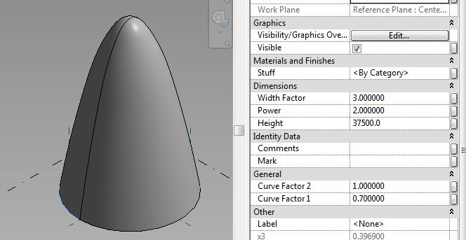
Now you make one family and you can vary the curve increasing the "power of Y" or the "power of X" depending on which way up you make the graph.  Of course, if the power is 1 you will have a straight line (X=Y)  If it was less than one you would get a concave form.


Use this curve in a massing family (or Generic Model Adaptive) to create a revolve.  Looks like a coconut macaroon.


Now lay a whole bunch of them out and vary the parameters in a systematic manner.  I've taken care to organise the parameters so just 3 of them display to the end user.  Here we are keeping the base width constant and varying the other 2:  power & height.


Of course you can generate much more variety by manipulating all three and taking them to extremes.


Here's a view that shows what we are doing more clearly.  I was quite excited by this, but if you look closely the curves are not quite smooth.  There is a certain amount of "necking" taking place at extreme values.  Unwanted bulges.


Seemed to me this was a result of not having enough points to hold the curve steady.  So I set about making a more finely divided rig, which gives me a chance to talk you through the process.

Two points created in an elevation view.  Labelled dimension gives me a height parameter.  Spline thru points joins them with a ref line.  Set the work plane to the vertical plane of each point in turn.  Place points on points, give them offset values.  Label these with a width parameter.  Complete the rectangle.  This is a classic rectangular rig.  See also the video on my Vasari Talk session.


I'm creating vertical rungs using Normalised Curve Parameter positions  that are assigned parameters (x1, x2, x3 etc)  Initially these create 10 equal divisions (0.1, 0.2, 0.3 etc)


Then I string a spline across these rungs.  These points get parameters too (y1, y2, y3 etc)  Now you can linke X & Y with a simple formula to generate a regular curve.  That's what I did before with 5 divisions.  Now I have a finer degree of control.


Power of 2 gives us a nice smooth parabola.


Power of 6 concentrates most of the curve in the "middle".  You get a relatively straight section, then a sharp bend, then an almost flat top.  This is where the anomalies start to show up.  At power of 9 the curve starts to reverse because there aren't enough points to hold its line. (see how it flares out slightly at the base)


I dealt with this by making the points closer together near the ends.  It's kind of like using a logarithmic scale on your graph.


All good, but what if I want the curve to go beyond the vertical.  This is what I did previously with the Gherkin  (see the link at the beginning of this post)  It's a bit of a hack, but it works.


So I set this up and created a much bigger array.


The results are quite interesting:


a wide range of forms ranging from Gherkin-like shapes to onion domes,


all from the same family and just by adding a 4th parameter called "Waist Height"


Want to take a look ?  Click on the link