OK, so the plan this weekend was to do a serious upgrade on the Lothbury facade. It's
taken me a while to really get to grips with all the source material and understand
how the building works, but by now it feels like an old friend so it's a good time to
start filling in the detail.

I started on Thursday night by turning the various sections of the facade into links.
There are pros and cons to this of course by I decided to bite the bullet. One of the
benefits is that different people can check out different portions for a couple of
days and work them up. On the down side it means that internal walls will not join to
the perimeter. It's not a problem when junctions are square, but in our case there
are lots of odd angles at work. I came up with a solution that I had never thought of
before. Probably it's old hat, but I was quite chuffed with it at the time.

Basically I created a new wall type, very thin, maybe half an inch, formed a join at
the right angle, then pulled my thin wall right back to the internal angle. You get a
sharp point one side and a little splay in the internal corner. I guess in some
circumstances you could use a different material and make it look like an isolation
joint.

So when I started on Project Soane, I had no idea about the "secret passage" around
the top of the screen wall and the troop of 30 soldiers who would turn up every night
to patrol the battlements. Now it is all falling into place, and what seemed to be
rather eccentric parapet embellishments turn out to be sentry boxes, placed at
convenient intervals to give the guys a bit of shelter on a rainy night. Not that
I've read about this anywhere, but it's perfectly obvious once you model things in
detail and pore over the drawings in the online archive.

My first challenge was the tradesmen's entrance, which is where the guardsmen would
enter the premises each evening. This was built as part of the NW extension somewhere
around 1805 and opened into a courtyard where Soane built a new barracks to replace
the one he had built more than a decade earlier when the Bank's backyard was much
further south. This is an almost identical copy of the bullion gateway he had
designed for the NE extension. Flanking the gate are two Antae (columned recesses)
Above each of these is a sentry box with an elaborately scrolled roof, and between
these a high wall at the back. This is necessary in the bullion gate to hide the
upper storey of the Porter's lodge, but in the tradesmen's entrance it's just there
for the sake of symmetry.

So I've set all this up, and you can see the route where the soldiers patrol, but it's
all a bit crudely modelled. No point in getting into detail until you understand
what's going on. For example, it's only this weekend that I understood that the
scrolls were extended back over the full width of the walkway to form roofs over
sentry boxes, and that there were archways passing through, all the way along. You
can actually see these arched openings in a couple of Soane's sections, but I didn't
grasp the significance at first.

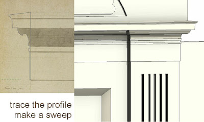
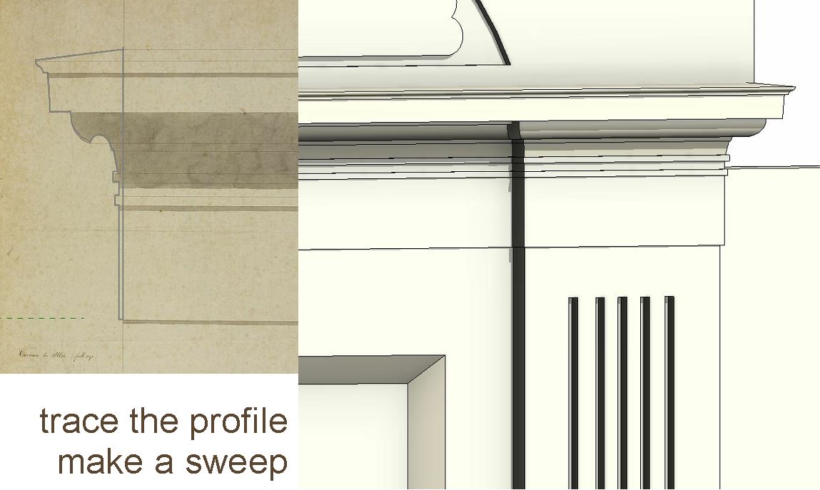
The corners of the sentry boxes have pilasters and there is a detail showing the
moulding profile. So I scaled up this image and traced over the profile. Notice the
undercut below the overhang to get the rainwater to drip clear of the wall face. You
can see Soane's trademark abstraction of classical form in the parallel ribs and
grooves.
The scrolls themselves were donated by Sheikh Uduman some time ago and have done
excellent service, but I've made some adjustments to the curves based on a more
careful reading of the source images. And of course they project back much further
and I've added some ribs in the depth of the section. I only have the grainiest of
photos to go on for this so it's pretty schematic.

Either side of each sentry box is an antefix. These are normally placed on the eaves
as if to stop tiles from sliding off. Previously I had just placed another of Soane's
"telephone box" items that march around the parapet at intervals, usually aligned
above a column or a blind window. The antefix is a bit similar but more pointy, and
directional. Also the plinth it stands on is more elaborate.

One family that was really fun to make is a recess with a moulding around the edge,
sort of like a picture frame. This is used many times: sometimes projected sometimes
flush, once as part of a pilaster. It's a simple, parametric, face-based family, that
works a treat; very satisfying economy of effort.
So we move on to the gateway itself. I did the fanlight first. Wrought iron, quite
delicate looking but simple enough. To me it reflects Soane's debt to the Adam
brothers whose work he admired. Here of course, Revit's dynamic radial arrays come
into play. They really helped me to fine tune the setting out without having to keep
drawing thing again from scratch.

The doors are typical Soane. Multiple panels, almost flush with lots of domed studs.
I came across lots of variations on this design during my short tour of his London
works. The current gate is very different (also in a different position by the way)
Baker lacked Soane's restraint, very fluent designer and prolific, but a classicist in
a different age, when modernism was already in full flower on the continent. I
digress.

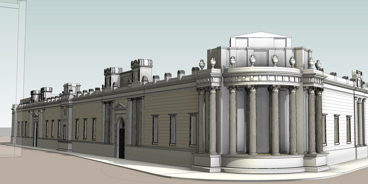
This whole feature projects forward slightly. I managed to capture this fairly well
in Revit. You can also see the archway into the Sentry Box here. Gives a sense of
scale. Baker recreated these Antae fairly accurately and subsequent restoration of
the stone has been pretty faithful over the years.

See how the pilasters wrap around the corners. I've captured this now, but not the
detail on the capitals. I think the recesses are shallower on Baker's wall. Probably
the whole wall is thinner. No longer needs to support a walkway around the perimeter.
So there isn't space for the base moulding at the back, which you can just see
peeping through in one of the old photos.

The other major feature I worked on is at the centre of Lothbury. This is placed at
what used to be the Junction of Princes Street and Lothbury. It's the hinge point
where Soane had to duplicate his facade, doubling the length to take hime to Tivoli
Corner. There are many surviving studies where Soane struggled over how to do this.
Some of them show a slight change of angle. In the end the solution is quite simple
and he managed to persuade his client to keep the whole frontage straight. A few
square metres lost, but ultimately a much more satisfactory layout.

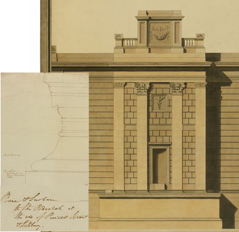
There is a drawing in the archive of a moulding that is described as "The working
drawing is for the base of a column, probably that of the blind portico on Princes
Street." going on to suggest that the note on the drawing itself must be wrong. It
wasn't till this weekend that the penny dropped. This is the moulding for the base of
the centre feature on Lothbury, drawn at the time when the street junction was here,
not where it moved to AFTER the wall was built. So I'm rather confident that the title on
the drawing is quite correct. "Base & Surbase to the Pedestals at the end of Princes
Street & Lothbury." It matches up perfectly, which becomes obvious once you model it
in Revit.

It's not always possible to draw something in one context in Revit and copy paste it
straight into another. To trace over this image in the project where I was modelling
and get it into a a profile family I had to use a masking region as an intermediary.
Not sure why we have to use these obscure work-arounds. Can be off-putting for the
beginner.

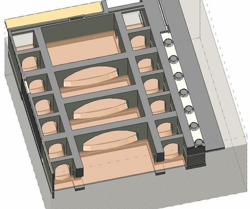
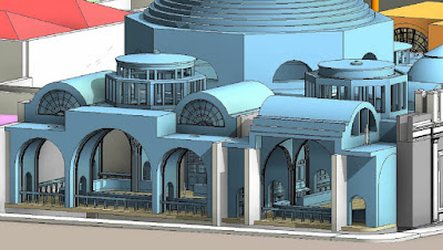
One side effect of turning the screen wall into a series of links was that whenever I
did an "open and unload" it revealed unexected views of the interior. Here is a
glimpse of his last two Transfer Halls from an unusual angle. I love this project.
It's a never ending series of revelations and challenges. I'm rather fond of the "Dolls House" effect of this particular image. Open the façade and look inside, see what all the imaginary people are doing.
So this hinge point has the one Sentry Box on top, starting out as a simple box with 4
walls and the archways passing through. Then you add pilasters at the corners. These
are the ones with my recess family embedded. Also more recesses placed on the walls.
Add in a furter variation on the acroterion theme, and a few moulding profiles ...

To polish off the weekend, I had a quick go at the Bartholomew Way facade. Once more
the battlements and sentry boxes suddenly fell into place. Mystery became common
sense and I had time to add my recess family in groups of 3.

By now, Paul Aubin had uploaded his new-improved Corinthian column. Quite a
heavyweight piece of stuff, created in the wonderful world of reference points. It's
based on the Generic Model Adaptive template, but changed to Column category, so
(mirabilis dictu) it just swaps out with my very simple placeholder using the type
selector. Flip of a switch. Magic. So in a few minutes I was able to update all the
links with detailed columns.

One of the drawbacks of point world geometry is that it is "adaptive" (also a great
strength of course) so it doesn't have a fixed location. In short, the new column is
not level-aware. It won't report what level it's on. Strange really, because the
moment you swap it back to my placeholder it remembers again. Another quirk is that
it gets very confused when mirrored and tends to stand on its head. So take your time
and copy things sideways instead of mirroring them.

That's about it. Couple more people working on bits and pieces for the exterior
facade. Thankyou guys, and you will be featured in an upcoming post. Crowd sauce is
beginning to spice things up a bit, I'm thrilled to announce. You can view the
current state of things by logging in to Project Soane. And of course there's lots of
room for more volunteers to contribute. If you're not sure where to start, just let
me know and I'll point you in the right direction.
We will prevail.

taken me a while to really get to grips with all the source material and understand
how the building works, but by now it feels like an old friend so it's a good time to
start filling in the detail.

I started on Thursday night by turning the various sections of the facade into links.
There are pros and cons to this of course by I decided to bite the bullet. One of the
benefits is that different people can check out different portions for a couple of
days and work them up. On the down side it means that internal walls will not join to
the perimeter. It's not a problem when junctions are square, but in our case there
are lots of odd angles at work. I came up with a solution that I had never thought of
before. Probably it's old hat, but I was quite chuffed with it at the time.

Basically I created a new wall type, very thin, maybe half an inch, formed a join at
the right angle, then pulled my thin wall right back to the internal angle. You get a
sharp point one side and a little splay in the internal corner. I guess in some
circumstances you could use a different material and make it look like an isolation
joint.

So when I started on Project Soane, I had no idea about the "secret passage" around
the top of the screen wall and the troop of 30 soldiers who would turn up every night
to patrol the battlements. Now it is all falling into place, and what seemed to be
rather eccentric parapet embellishments turn out to be sentry boxes, placed at
convenient intervals to give the guys a bit of shelter on a rainy night. Not that
I've read about this anywhere, but it's perfectly obvious once you model things in
detail and pore over the drawings in the online archive.

My first challenge was the tradesmen's entrance, which is where the guardsmen would
enter the premises each evening. This was built as part of the NW extension somewhere
around 1805 and opened into a courtyard where Soane built a new barracks to replace
the one he had built more than a decade earlier when the Bank's backyard was much
further south. This is an almost identical copy of the bullion gateway he had
designed for the NE extension. Flanking the gate are two Antae (columned recesses)
Above each of these is a sentry box with an elaborately scrolled roof, and between
these a high wall at the back. This is necessary in the bullion gate to hide the
upper storey of the Porter's lodge, but in the tradesmen's entrance it's just there
for the sake of symmetry.

So I've set all this up, and you can see the route where the soldiers patrol, but it's
all a bit crudely modelled. No point in getting into detail until you understand
what's going on. For example, it's only this weekend that I understood that the
scrolls were extended back over the full width of the walkway to form roofs over
sentry boxes, and that there were archways passing through, all the way along. You
can actually see these arched openings in a couple of Soane's sections, but I didn't
grasp the significance at first.

The corners of the sentry boxes have pilasters and there is a detail showing the
moulding profile. So I scaled up this image and traced over the profile. Notice the
undercut below the overhang to get the rainwater to drip clear of the wall face. You
can see Soane's trademark abstraction of classical form in the parallel ribs and
grooves.
The scrolls themselves were donated by Sheikh Uduman some time ago and have done
excellent service, but I've made some adjustments to the curves based on a more
careful reading of the source images. And of course they project back much further
and I've added some ribs in the depth of the section. I only have the grainiest of
photos to go on for this so it's pretty schematic.

Either side of each sentry box is an antefix. These are normally placed on the eaves
as if to stop tiles from sliding off. Previously I had just placed another of Soane's
"telephone box" items that march around the parapet at intervals, usually aligned
above a column or a blind window. The antefix is a bit similar but more pointy, and
directional. Also the plinth it stands on is more elaborate.

One family that was really fun to make is a recess with a moulding around the edge,
sort of like a picture frame. This is used many times: sometimes projected sometimes
flush, once as part of a pilaster. It's a simple, parametric, face-based family, that
works a treat; very satisfying economy of effort.
So we move on to the gateway itself. I did the fanlight first. Wrought iron, quite
delicate looking but simple enough. To me it reflects Soane's debt to the Adam
brothers whose work he admired. Here of course, Revit's dynamic radial arrays come
into play. They really helped me to fine tune the setting out without having to keep
drawing thing again from scratch.

The doors are typical Soane. Multiple panels, almost flush with lots of domed studs.
I came across lots of variations on this design during my short tour of his London
works. The current gate is very different (also in a different position by the way)
Baker lacked Soane's restraint, very fluent designer and prolific, but a classicist in
a different age, when modernism was already in full flower on the continent. I
digress.

This whole feature projects forward slightly. I managed to capture this fairly well
in Revit. You can also see the archway into the Sentry Box here. Gives a sense of
scale. Baker recreated these Antae fairly accurately and subsequent restoration of
the stone has been pretty faithful over the years.

See how the pilasters wrap around the corners. I've captured this now, but not the
detail on the capitals. I think the recesses are shallower on Baker's wall. Probably
the whole wall is thinner. No longer needs to support a walkway around the perimeter.
So there isn't space for the base moulding at the back, which you can just see
peeping through in one of the old photos.

The other major feature I worked on is at the centre of Lothbury. This is placed at
what used to be the Junction of Princes Street and Lothbury. It's the hinge point
where Soane had to duplicate his facade, doubling the length to take hime to Tivoli
Corner. There are many surviving studies where Soane struggled over how to do this.
Some of them show a slight change of angle. In the end the solution is quite simple
and he managed to persuade his client to keep the whole frontage straight. A few
square metres lost, but ultimately a much more satisfactory layout.
There is a drawing in the archive of a moulding that is described as "The working
drawing is for the base of a column, probably that of the blind portico on Princes
Street." going on to suggest that the note on the drawing itself must be wrong. It
wasn't till this weekend that the penny dropped. This is the moulding for the base of
the centre feature on Lothbury, drawn at the time when the street junction was here,
not where it moved to AFTER the wall was built. So I'm rather confident that the title on
the drawing is quite correct. "Base & Surbase to the Pedestals at the end of Princes
Street & Lothbury." It matches up perfectly, which becomes obvious once you model it
in Revit.

It's not always possible to draw something in one context in Revit and copy paste it
straight into another. To trace over this image in the project where I was modelling
and get it into a a profile family I had to use a masking region as an intermediary.
Not sure why we have to use these obscure work-arounds. Can be off-putting for the
beginner.

One side effect of turning the screen wall into a series of links was that whenever I
did an "open and unload" it revealed unexected views of the interior. Here is a
glimpse of his last two Transfer Halls from an unusual angle. I love this project.
It's a never ending series of revelations and challenges. I'm rather fond of the "Dolls House" effect of this particular image. Open the façade and look inside, see what all the imaginary people are doing.

So this hinge point has the one Sentry Box on top, starting out as a simple box with 4
walls and the archways passing through. Then you add pilasters at the corners. These
are the ones with my recess family embedded. Also more recesses placed on the walls.
Add in a furter variation on the acroterion theme, and a few moulding profiles ...

To polish off the weekend, I had a quick go at the Bartholomew Way facade. Once more
the battlements and sentry boxes suddenly fell into place. Mystery became common
sense and I had time to add my recess family in groups of 3.

By now, Paul Aubin had uploaded his new-improved Corinthian column. Quite a
heavyweight piece of stuff, created in the wonderful world of reference points. It's
based on the Generic Model Adaptive template, but changed to Column category, so
(mirabilis dictu) it just swaps out with my very simple placeholder using the type
selector. Flip of a switch. Magic. So in a few minutes I was able to update all the
links with detailed columns.

One of the drawbacks of point world geometry is that it is "adaptive" (also a great
strength of course) so it doesn't have a fixed location. In short, the new column is
not level-aware. It won't report what level it's on. Strange really, because the
moment you swap it back to my placeholder it remembers again. Another quirk is that
it gets very confused when mirrored and tends to stand on its head. So take your time
and copy things sideways instead of mirroring them.

That's about it. Couple more people working on bits and pieces for the exterior
facade. Thankyou guys, and you will be featured in an upcoming post. Crowd sauce is
beginning to spice things up a bit, I'm thrilled to announce. You can view the
current state of things by logging in to Project Soane. And of course there's lots of
room for more volunteers to contribute. If you're not sure where to start, just let
me know and I'll point you in the right direction.
We will prevail.