Thursday, October 27, 2011

PUMPKIN POSTSCRIPT

So what have I learnt ?

 A lot ... never imagined where this jounrney would take me.  But let's stand back and reflect.  The basic premise of this exercise has been that pumpkins and doric columns can be treated as homologous structures.

METAMORPHOSIS
This is the essence of parametric families.  I could easily now make a family that has 2 types: a pumpkin and a doric column


Not something I would use directly, but I suspect that the techniques developed here will have many applications. Plumbing & furniture families that can morph into different sizes and shapes perhaps. 


SIMPLICITY (BOILING DOWN THE PUMPKIN)
I tried hard to simplify and organise my dialogue boxes, but I think they would still be pretty scary to the average user.  What should the Type Parameters Dialogue for a Doric Column family look like in an ideal world ?


BIOMIMICRY
Revit is good at making shapes based on rules.  But we also need to deal with the other end of the spectrum : soft, lumpy, irregular things.  You can use an FBX workflow into Max.  You can fake stuff in photoshop.  But you can also introduce some irregularity of shape & texture in Revit.  There is a long way to go though.  Think thatched roofing, & rough stone walling.  Not easy to do convincingly in Revit.
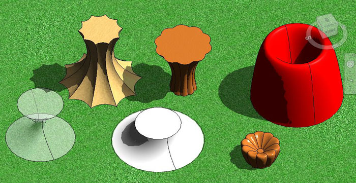

FILES
So it's been a long week and here in the desert our weekend started 5 hours ago.  Time to upload what I have and leave the rest to Zach.  File is  HERE .   2012 version this time.  Contents pictured below.


INTO THE VOID

Post 5 for the Pumpkin Competition.  Need to start carving.


To hollow out the middle we could use a revolve.  Conceptual massing doesn't have a separate revolve tool, just draw an axis line and a closed loop like you would with the normal revolve tool, and "make void form".


So how about the eyes ?  Make a triangular profile that is resizeable in a separate mass family.  Load into project. Draw lines radiating out from the centre of the pumpkin, add angle parameters. Host a point on those lines, make reference plane visible, place triangle on plane.  Selec line & triangle, make void, Revit knows it's a sweep.


Let's pause here.  Is anyone else getting worried ?  It's all getting too messy.  How am I going to link all this together so it resizes as a unit ?  What does it equate to in the real world ?  Let's back up a bit and try something a bit simpler. 

Imagine we want a hollow Doric column (precast or GRP maybe)  All we need is another set of profiles, scaled down by a factor and used to define a void. Probably we want a smooth circular void. We already have a circle profile in this family, so it's easy to create another 3 types and link their radii to the outer profiles.  This is nice, because we only have one more parameter for the end user to worry about.  I called this "Void factor" and set it to 0.8    Inner Radius = Outer Radius x Void Factor


The result is still quite robust and versatile.   I spent a little time on the dialogue box organisation & parameter naming. I've made an effort to arrange things logically and think about ease-of-use, but probably it could be distilled down further.


Need to be careful with the convex "pumpkin" versions because the shell can get too thin and the family breaks.  Maybe we could find a way of linking the bulge factor & void factor together to avoid this.  Clearly the re-entrant forms are going to be difficult, but there is potential here.


There's been a dynamic going between organic & geometric, make-it-look-like-a-pumpkin v do something useful & interesting, one off originality v the common good.  And if I really wanted to make a pumpkin that is convincingly real, re-sizeable, with optional carved voids, I'm probably more than half-way there. 


But the offshoots and by-products are too rich to ignore.  So I let myself get carried away for a while. . There is a treasure-trove of semi-automated form finding on my doorstep now,  with copious references to flowers, jellyfish, starfish, lemon-squeezers ...    I'm also well on the way to a whole battery of classical column families.


Perhaps this whole exercise with its flip-flopping between pumpkins & columns is an apt metaphor for architecting in general.  Oscillating back and forth between what we would like & what we can afford

Wednesday, October 26, 2011

MUSHROOMS & MICE

Post 4 of our Pumpkin Competition.


This one is just a series of random doodles.  What else can I do with profiles ?  How do I make a more realistic stem ?  Hey that looks like a mushroom ! 


Place 5 points on a vertical plane. Make a spline-by-points Set their work planes to always show. Host the 5 profiles on these planes.  (took a bit of coaxing)  Play with different radii and move the points about manually (push-pull)  Make the top two points adaptive (shape handle


Now I can take it into the project and fiddle with how the top of the stem curls over.  All a bit sluggish (delayed response), but quite interesting.  I've reverted to using 2011 so that the downloads will be more accessible.  This means the adaptive component has to be placed in an in-place mass family, not directly in the project.  No big deal.


Oops, now Florence is back, and the cat too.  Looks like a stage set with a painted backdrop, it's a problem we often face with RPC content: wonderful clever stuff, but watch out for the 2 dimensional give-aways.  Still, it gives me a chance to show off a bit in photoshop.  who wants a totally photo-real world anyway ?  And there's carving too, not parametric yet, but real pumpkin-face carving.  I love the way that Alice & Florence both seem to be staring at the Cheshire cat.  Maybe there are mice hiding in the pumpkin.  Something's making kitty's eyes light up.  It's also quite neat how the water-colour effect makes the two RPC trees blend with the background image.


OK, so I've added the mice, and it's all getting a bit silly.  But the point is that sometimes these "random accidents" can point to serious possibilities.  We are always playing in the space between image and reality, 3 dimensional experience & 2 dimensional diagram.  It's largely a question of how you navigate back & forth between these different worlds.  And suddenly I'm reminded of the most prosaic example.  Bannister Fletcher's page on the Doric Order.


Once again it's the juxtaposition of different scales and modes of drawing in order to compress a complex information set into a single image.  For sure BIM is changing our world, and we have to open our minds to new possibilities, possibly the demise of the "construction drawing" as we know it, but let's also remain alert to unexpected parallels and lessons from the past.

Tuesday, October 25, 2011

GOING ORGANIC

Post number 3 of my pumpkin carving competition entry.


OK so the first image is a nice diagram that Wil sent me. It explains the derivation of the formulae in his original family. Now I understand better what he was driving at.  Probably more scientific than my "Bulge Factor" approach, but I'm going to persevere for the moment with my nested profiles.  In fact I'm going for a "Five Stack" this time around.


You may notice that the profile family looks neater now.  I've got the whole "select-filter-copyrotate" routine down now. But that's probably a separate post.


Using 5 profiles is a bit more hard work, but it gives me more options for sculpting the shape.  This time I want to focus on a more realistic, organic looking pumpkin.  So this represents the opposite pole to that whole Doric, pure-geometry approach to Design.

Now I'm getting a rounded volume with a depressed centre. But it's still too regular.


I can play with the render settings.  Give it a bump map.  This one is based on the Leather Fabrics, but with the depth of the bump map cranked up.


Looking at images of pumpkins I got the feeling that my segments were too regular. So I made another profile, being deliberately sloppy with the setting out.  This is better, but I need to give one or two segments an extra bulge.  I also reached into my bottom drawer for a render texture image that I made a while back to simulate old walling  (we do resorts that capture the feel of a desert village, see this link :  Bab al Shams by GAJ  )  It has a large-scale blotchiness.


Rendered up, the result is starting to get there. The stack of 5 profiles also gives more control over the stem.  I can keep most of it thin then just bulge out quickly at the base.  No way to achieve that with only 3 profiles. Would be better if it curved to one side, but that needs a different family with profiles swept along a path.  While I am busy messing with the render settings I sneaked in a background image from the bit in Cinderella where the fairy godmother transforms the pumpkin into a carriage.


I haven't used the background image in renders much before.  I like the way the automatic sky responds to different times of day.  Flat images of the sky tend to look a bit ... flat.  But perhaps there is scope for using images in a more diagramatic context.  It's OK to be flat when you are not trying for that ultra-photo-real effect.

In the end, everything we do is a diagram, and sometimes a simple thumbnail sketch is the best way of communicating an idea. We should spend more time thinking about what is the BIM equivalent to this.


  The massing tools are one approach, but there must be many others.  Just because it's an intelligent 3d model it doesn't have to be so complex that you can't see the wood for the trees.  For example, a while ago I made a Revit version of one of Corb's simple diagrams.  "Less is more" as a cigar-smoking German once said.

Monday, October 24, 2011

WHEN IS A PUMPKIN NOT A PUMPKIN

This is post no 2 of our competition entry.  Zach is watching, so behave yourselves.


Pumpkins are well know for their metamorphic properties as Cinderella would be quick to point out.  I haven't quite got the coach & horses down yet (still looking for some suitable mice) but the transformations are proceeding apace.


First off was the 20 volute column. Turned out to be quite easy to filter-select and copy-rotate elements to double up the number of points and parameters in my profile.  Had to dissolve it first of course and later on select the points, 3 at a time, to do the spline-by-points trick again for each of the 20 volutes.


After that it's a question of creating a parameter for the profile name, so we can choose what to use for base, mid and top.  Then associate the radii with parameters R1, R2 & R3 so that I can control the size of each profile from within the host family. Hey presto you get a really nice scaleable Doric column shaft from the same family that made the original pumpkin,


So far this has been done in a Generic Model "Adaptive" family.  So it can be converted to another category, EXCEPT for mass.  To prove the scaleability I set up another version of the family by loading my profile into a conceptual mass family template. Jack this up to 75 metres high with a base diameter of 10m and we're away.


The base was modelled in-place, mass-floors put in, and then straight on to wall-by-face.  Click, click, click go my 20 volutes.  I tested out changing the size of the mass family and using "update to face", works fine.  Windows go in, copy them up from floor to floor, no problem.  Half an hour and I have the basic shell of the building done.


The two doric columns at the main entrance are metamorphosed pumpkins, 3 times over.  Confused ?  Simple.  One for the shaft, one for the echinuus (based on a cirular profile) and one for the abacus (square profile)


So by now I have 4 different profile families loaded into my pumpkin host, and by playing with parameters I can create all kinds of forms, including re-entrant shapes. And pumpkins of course.


How about egg-cups, golf tees, crown-of-thorn cathedrals ... lots of possibilities here


I'll finish with a render of the Tribune scheme by Loos. The windows are not quite right yet, and there should be 28 volutes, not 20. Seems he cheated a bit to get the plan to work. (been there) 


I guess you could count the windows as "carving", but I'd like to do some parametric voids that do clever stuff. Any ideas ?


If you want to contribute, you can pick up my parametric doric pumpkin family form here.
Anything half decent will get included in my next post.

5 stack pumpkins 2011

Actually this is the 5 profile version, opens with Revit 2011 & later.  More about that tomorrow.

Sunday, October 23, 2011

EXPLORING PUMPKINLAND


I was going to leave this to the last minute so as nobody else could pinch my ideas, then I thought "why are you doing that ?  If you really believe in open collaboration you need to put it out there and see what happens"  After all this is inspired by Wil from the land of windmills & legalised marijuana who read my "Lunch with the Gods" piece, and took up the challenge to make a parametric Doric column.


I opened this up on Thursday and was truly inspired.  Lots of parameters whose names obviously make sense in Dutch, and formulas that I only half understood, but the result is a doric column shaft that you can resize at Will (as it were)  A great big thankyou to Wil for contributing a family to the Shades of Grey community.


Now it so happened that Wil mentioned that he got part of his inspiration from Zach Kron's blog.  Just about everybody who uses the conceptual massing tools has been inspired by Zach, but this jogged my memory that the 3rd annual pumpkin carving competition is imminent. 

Lightbulb moment.  Wouldn't take much tweaking to make a parametric doric column morph into a pumpkin.


So on Thursday afternoon (in between Revit training with Ignacio, John & cezar and making a door family for Sabu)  I played out another hunch.  David Light posted a while back about using profiles in conceptual massing.  Why couldn't I convert Wil's family into mass profiles nested inside an adaptive component.  3 Profiles with variable radii, (placed on 3 separate workplanes) would surely give me what I was looking for.


The first attempt didn't work because Will had used reference lines (very cleverly) to create the rig for his profile.  That's OK as long as the profiles are created directly in the family. You can select the lines you want to use to create a form. But I thought it would be more elegant to nest the profiles.  Problem is Revit tries to create a form from every line or reference line within that nested family.  Turns out though that you can host points on reference PLANES, and still set up parameters to control them.  You need quite a lot of dimensions, (and to tab them to snap to your points), but it works fine.


HINT: use a mass family to create the profile.  Don't try to use the profile family template like you would for railings etc.  The 3 profiles give me nice entasis on the columns, and I can reverse this to create a stalk for the tops of my pumpkins.  By using a "bulge factor" to set the ratio between the two imaginary diameters, I can reverse the curve from convex to concave.  A ratio of 1.2 is concave and 0.8 is convex.  You are just playing with whether the points for the centres of the curves are inside or outside the end points.


For a proper Doric column you need 20 volutes, but I wanted to test my idea first so I set up 10, which is more realistic for a pumpkin in any case.  So there are still a few days to go before Halloween.  Where should I take this next ?  I am thinking ... OK we have an interesting jump in scale from the pumpkin you buy at the corner shop, via giant competition pumpkin, small column in your garden ... whopping big column at Paestum.  Why not jump again ?  Massing is supposed to be a framework for early design of multi-storey buildings, so why not do Adolf Loos' 1922 entry for the Chicago Tribune Tower competition.


Any other ideas out there ?  We could have a competition within a competition.  How about the carving aspect ?  I haven't done any of that yet, apart from the Cheshire cat grins I faked in photoshop.  There must be a cool way to cut parametric voids into my family.  Remember it would need to scale up with the rest of the family somehow.

Wednesday, October 19, 2011

HITTING THE CEILING

Got a comment from Julio a couple of weeks ago asking how to make a recessed lighting cornice.  See   beam-me-up-scotty

I thought this would making an interesting little tutorial for my guys and featured it in one of my Revit Lunches, but since then things have been a bit crazy and I forgot all about it.  Stumbled across it again today by accident and decided to turn it into a post.  Bit rough and ready, but hope some of you find it useful.


This is the (almost) finished article.  Should put another light fitting in there to kill the dark spot, but I need to go home to get some sleep so I'm not going to re-make this image today. 

This is a ceiling hosted family so go to new family, & choose the ceiling hosted template.


Set up some reference planes with equalised width & length parameters.  Create an "opening" and lock the sketch to the ref planes.  Might as well make width & length instance parameters so you can easily stretch it to different sizes. 

Next we need an extrusion for the sides.  This will be a rectangle locked to the same reference planes and "copy-offset" by say 20mm so that we get a hollow box around the edges of the opening.


Go into a side view and create reference planes for the height of the box and the thickness of the upper ceiling board.  Then back to plan view to create another extrusion for the upper ceiling.

By now you have 3 objects all locked to the same reference planes. You want them all locked to the reference planes, and not to each other, otherwise you might get that nasty message saying you have a circular chain of references.

A simple way to handle this, is to hide the other objects with the sunglasses (temporary hide) tool while drawing the sketch for each extrusion. That way you can only see the reference planes so you know that is what you are snapping to.


Now we want a cornice moulding.  This is a sweep and the path is locked to those same 4 reference planes once again.  The profile could be sketched directly in the family, but I prefer to load a profile family.  That way I can set a parameter to choose between loaded profiles.  Now the family is very versatile within the project.  You can set up types with different heights and moulding profiles, and instances with different dimensions in plan.


This is one profile that I created which can be resized using just 2 parameters.  Check out the visual below for how this is achieved.


The lights can be loaded directly in the project and placed behind the cornice.  I used the "M_Uplight - Strip" family supplied with Revit Architecture.  One last tip.  To set the equality constraints on the ogee curve in the profile family, you need to "tab select" to persuade the dimension tool to pick up the end point of the arc.

Download the family here :   coffer family