Sunday, January 22, 2012

GOLF IN THE GULF

I set out this weekend to make my first screen capture video.  Please don't laugh, I will get better with practice.  I decided to make a fairly simple parametric mass family such as we might use in early design development, and the building that sprang to mind is one that my good friend (and boss) Brian Johnson designed early in his career, here in Dubai.


The Club House at Emirates Golf Course is designed as a cluster of tents, symbolising the Majlis course which was seen as something of a miracle at the time, being an all grass, championship golf course in the middle of the desert.  Since then a second 18 hole course has been added, and the desert has given way to a dense forest of office & residential towers, not to mention several hotels.
I'm pretty sure this was a hand-drawn project, probably with much fewer drawings than the enormous sheet sets we churn out these days.  How different the world is just 25 years later.  It would be interesting to take this simulation of early design development a little further using the Emirates Club House as a case study.


On a completely different topic, I talked to a contractor last week who was complaining about having to take Architects 2d CAD plans and convert them into BIM models in order to anticipate coordination problems on site.  I've had similar stories from Engineers who have been the lone Revit pioneers in a design team.  Needless to say we are GAJ have been struggling with the need dumb down our Revit models into flat DWG for clients, engineers and contractors.  Let's hope the Arab Spring of Revit is approaching.


So back to the videos.  It comes in 3 parts, and the links are here.

PART 1

PART 2

PART 3

You can also download a project with the massing family arrayed in 3 different configurations here.

Tent Mass

Thursday, January 19, 2012

THE OTHER SIDE OF ME

You may have noticed it says "Blues Musician" at the end of the "about me" stuff under my photo.

Well I finally got around to making a music video & posting it to You Tube.  I'm usually the last person on the planet to latch on to new technologies, so don't get too surprised.

http://www.youtube.com/watch?v=RgABjqiqtQk&context=C339cbccADOEgsToPDskJA_Kjd5NrM1UWAqvhZKpt4

Now that I've started there will be more ... and I promise to start doing Revit videos too ... maybe even this weekend.

Here's a pic from what will probably be my next music upload.  Just solo stuff at the moment, but maybe I'll manage to capture my small band too.


Heading for home now (honest)

Sunday, January 15, 2012

UP THE GARDEN PATH

One of my little hobbies is to plug away in areas where Revit is notoriously weak, in the belief that things are not always as bad as they seem.  For example my attempts to create better families for toilets & washbasins.  Stairs and railings are also obvious targets.  Another common complaint is the lack of tools for creating roads and footpaths.  There is a 3rd party plug-in that you can buy (Eagle Point).  I haven't had a chance to try it out but Aaron Maller has done some very interesting work with it.  malleristic revitation


My challenge for last weekend was to try to squeeze some extra performance from out-of-the-box tools like ramps, floors & railings.  Revit ramps are a mixed blessing.  They rarely display as you would like them to in plan views, which I find very puzzling.  Like stairs they are designed to go from level to level using preset rules, which makes them a bit cumbersome to use as footpaths.  But let's try.


Imagine a drop-off point on a slope.  The pavement around the edge needs a kerb and a set of regularly spaced bollards.  The first point to note is that risers are divisions between sections of sloping ramp and flat landing. To go from straight ramp to curved ramp you can omit the riser or place two risers in the same place.  Oddly enough the second option works better.


The fill pattern on a curved ramp will adapt to the curve. A square grid becomes a radial pattern for example.  Also the railings will follow the slope of the curve very nicely.


But if you use a floor with a slope arrow, the grid remains square & the railings won't quite match the slope.  You can see this clearly at the junction between floor & kerb.  The kerb is a simple rail, and the bollards a series of balusters.  You can force the slope arrow to follow a curve using the pick option, but it makes no difference, the floor will remain flat, and the bollards will float above it in the middle even though they touch at both ends. 


Also take care how you draw the railing.  The slope is determined by the start and end points of each segment.  In this case, rotating the sketch by 90 degrees creates a very different result.


 The shortcomings of the ramp tool are well known.  You need to do a lot of drafting to get the appearance you want in a plan view, and in section it's probably worse.  There is no "edit structure" to add a finishes build-up and no "join geometry" to clean up the junction with the clever railing you invented to emulate a curved parapet wall.


It's great that they have the intelligence to respond to maximum slope settings and automatically prompt you into placing landings at the stipulated intervals.  Could be a great tool with a little extra functionality.  But stairs & ramps both suffer from one of their common strengths.  They are defined in relation to levels.  That's fantastic most of the time, but if you want to use them as landscape objects it becomes an annoying restriction. 


 So for a road flyover that has varying curves & gradients I choose ... in-place modelling, yet again & that wonderful invention that we got so excited about in the days before conceptual massing THE SWEPT BLEND.  Make a profile for your bridge cross-section.  Use it in a series of swept blends and tweak the curves and the levels of each profile to your hearts content.  Not very hard to create graceful bridge forms with a bit of practice.


 Almost looks like Dubai.  Notice the W-beam crash barrier.  Make yourself custom railing profile & baluster post families, define yourself a new railing type and away you go.


The quick and dirty solution for roads and footpaths is the topography subregion.  No kerbs of course, but they will follow the terrain and they are quick to make.  Also nice for golf courses, cricket pitches, flower beds ...  Pads are better for water of course because liquids tend lie flat.

At this point I was having so much fun I got a bit carried away and tried to make an adaptive family for a fence that would curve and swoop, twist and wind ... imagine the possibilities. 


Step one was a very simple mass family.  Just a vertical line with the "always vertical" parameter checked (family category & parameters)  Load this in to another mass family and host a bunch of them on adaptive points.  I figured out how to lock them in place so they moved up and down as a unit.  Fantastic.  Select the lines, create form, divide surface.  Problem solved.  (not)


Worked fine in the family environment, but that is not always a good indicator.  Soon as I loaded it into a project it broke.  Almost broke my heart.  But then I had another thought ... what about modelling in place ? 


So I followed the same strategy but this time all the adjustments are done by editing the family, so no opportunity to break.  I was so chuffed.  The posts and rails are curtain panels by pattern of course, based on the rectangular template. 


One day I will get round to exploring a range of different fence styles by setting up different panels, but for now I will quickly skip forward to my last brainwave of a rather productive weekend: image processing without rendering.  Not the answer to every situation, but could be a useful timesaver, and there is surely potential for batch exporting plus some automation within the image editor.  Could become a veritable production line & all thanks to "realistic" views.


I'm not a big fan of the realistic view.  Tends to look garish.  Somehow the material settings that work well for rendering are often too strident when viewed in "realistic".  But that's exactly where a bit of image processing can help out.  Combine a realistic with a shaded or hidden line, use an overlay setting, some transparency and/or an artistic filter.  Instant touchy-feely ... what more could you want ?

Thursday, January 12, 2012

UPSTAIRS DOWNSTAIRS

So last weekend I was playing on the stairs again.  This time I wanted to extend my use of the system stair tool.  No fancy conceptual massing tricks allowed.  So the obvious place to start was the spiral stair that I did a couple of posts back.  It turned out that I could create something very similar.  Slightly less control over the shape of tread, but much easier to place 2 balusters per tread, which is more realistic in terms of safety, regulations etc.


The support brackets are of course modelled as railings by creating a customised baluster family.  The stair therefore has two railings, one set to two balusters per tread, the other to one.  I will return to my adaptive stair shortly and demonstrate its ability to offer much more variety in tread design.  In the system tool you only have a single riser line to define the shape of the tread, but in my adaptive family you can basically model any shape of tread you like.


So the next little exercise was to explore different tread shapes using the system stair tool.  I made an elliptical stair and gave it treads with an "S curve".  This is quite straighforward but you need to set your geometry out carefully.  I drafted it first using detail lines, then traced over with the pick option.  The second stair is even simpler to make, but an interesting exercise all the same.  The bottom few risers are splayed, and the boundary on one side has to step and splay.


This made me think of Michelangelo's famous stair in the lobby to the Laurentian library.  I took this step by step (to coin a phrase) starting with a straight flight and progressively modifying it.  This is often a good approach so that when you inevitably receive the "can't make monolithic stair" message, you can go back to the previous stage and try again.


Eventually I was able to model something fairly convincing and then I just had to quickly rough out the tall square room that surrounds it.  I will do another post on this once I have developed it further.  Had fun with the balustrade too, all done with the normal railings tool, 2 different custom balusters, (one set to be a post at beginnings and ends) and one custom handrail profile (the bottom one is rectangular)


Just to polish off the weekend I decided to try making an ampitheatre.  Looking through my archive I came across the Theatre of Marcellus, also in Rome.  This turned into a fascinating exercise in stairs and radial arrays.  I simplified the geometry a bit so as to make the most of the array tool.  Worked like a treat.  I love the way that arrays in Revit remain "alive" so you can adjust your design as it develops. 


There are 4 or 5 different radial arrays to make up the seating and the access stairs that fit between the wedges.  For each one you keep adjusting the radius and the number of elements. Also by tabbing in to a single element and editing that group, you can adjust the instance properties of that stair, (where it starts & finishes, desired number of risers)  This was a very powerful way for me to explore the way a Roman theatre works. 


Again the surrounding structure is a possible future post, but you can get a glimpse of the way this is also largely composed of a series of live radial arrays that allow you to adjust the spacing and size of archways, column arrays etc until you are happy with the proportions and relationships. Parametric modelling at its best and all very basic Revit stuff that's been hardwired into the programme since forever.


Lest you think I am giving the stair tool to easy a ride let me finish with some grumbles.  We all know that monolithic stairs don't work properly.  They don't join to floor slabs (which is an absolute paint in the posterior) and if you want curved risers, be careful not to curve too far or they will start to cut into each other.  As for sketch mode.  It is very clever, but sometimes it just does its own thing, especially when you have a blue "run" in there.  Intermediate risers don't need to be cleaned up, which is a time saver, but make sure you clean up all the corners.

Sunday, January 8, 2012

OUR LADY UP THE HILL

This is the second of (probably) several posts on Le Corbusier's famoul pilgrimage chapel on the hill overlooking the village of Ronchamp. As source material I had quite a lot of photographs and several drawings, in jpeg format. These can be dragged into Revit and scaled up to life size. I estimated the size based on Google Earth & started tracing over a plan.


The curved walls are generally irregular and asymmetrical, For simplicity of construction I have compromised a little, but to maintain the feeling broken them down into short lengths with different radii. I'm using real walls, not extrusions, because eventually I want to cut sections and see the thickness of the roughcast plaster. The South Wall is an exception. This tapers and curves, rising to a sharp point at the South East corner so the wall system tool is not an option. I used in-place massing, starting with a blend, then adjusting with push-pull.


The west wall is curved in plan with an irreglar curve along its top edge. Edit profile won't work on curved walls, so I made a wall hosted family with a void cut, using a spline for the lower edge, and adjusting it by trial & error. The same method was used on the east wall.


I made the chapel walls symmetrical about an axis so that the half-domes could be in-place revolves, picking the top edge of the wall to make the profile. This is not quite accurate. The tops of the domes seem to be slightly flattened. But I think its an acceptable trade-off.


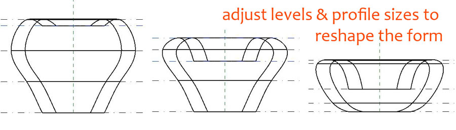
Not everyone realises that this building is based on a regular grid. Actually Corb nearly always used a rational grid. I set the grids up and used them as reference planes for a series of splines within an in-place mass. I read a post last week where someone wanted to abolish in-place families. I didn't find much use for them when I first started with Revit, but on a project like this they are indispensible. Select the splines and hit "create" to make a surface.


One of the splines is placed on a reference plane (not a grid). This can be rotated to fine-tune the angle. The whole surface can be adjusted while in edit mode by tab-selecting the splines one by one and adjusting the control points. I set up several perspective views to match photographs & just kept tweaking until it looked OK.


There is a void cut to form to remove the excess around the North-West corner. I tried to use roof-by-face to create an element with thickness, but it refused. This is unfortunate because I was hoping to attach some of the walls to the roof.  Strangely enough, wall-by-face worked, so the roof is actually a wall as far as Revit is concerned.


At this point I had a light-bulb moment. I don't know why it's taken so long to think of this. For over 6 years I have been hiding and unhiding section boxes in the view, simply because I find the solid lines annoying and confusing. My light bulb said, go to object styles and make them grey dash. No longer obtrusive and annoying. This is going into my standard template. The other penny that dropped was to do with the roof construction. The more I looked at my reference material and thought about the structural properties of this roof, the more I realised it must be a hollow double skin construction with vertical ribs along the lines of my splines.


The ribs must line up with the concrete columns. There are photos taken during construction which show the column and beam arrangement for the south wall. The infill is semi-coursed stonework salvaged from a previous building. I made the columns as a loadable family with parameters to adjust the base width either side of the point of support.


I realised now that my first attempt at the south wall was inaccurate, so I rebuilt it, this time as a series of vertical profiles hosted on the faces of the columns. I gave them a 50mm offset to allow for the thick roughcast plaster finish and that worked fine. By setting the wall to ghost surfaces in a view you can see the relationship between concrete framing and masonry infill.

Creating the tapering voids for the windows is not so easy. They are blends of course, but because the wall itself is tapering they tend to get distorted out of square. I tried to solve this by drawing on the plane of the wall, but the wall is not a flat plane, so you have to create reference planes that approximates the interior & exterior surfaces of the wall. This worked fairly well, but I need to go back and set it up more carefully when I have more time.


The North Wall was much easier. I modified one of my simple window families so that I could control width & height by instance. (every window is different, so no point in creating types) Then I set up an image and a revit view side by side on my screen and eyeballed the whole thing. Good enough for first pass.

By this stage I had become interested in the site context and created a toposurface around the building.  This was all based on guesswork, but later, (after I discovered the google earth trick) I created topography for the hill and surroundings.  I was also adding more and more detail.  The floor inside actually follows the slope of the site, then steps up to create a low platform for the altar. 


As an illustration of the way that making a BIM model leads to a deeper understanding of a building, check out the stair on the North Wall that leads up past a green door to a red door. 2 storeys up.  There is a cutaway perspective that appears in many text books, copied repeatedly by different artists including the redoubtable Francis Ching (No offence, I love his work).  Because of the cut plane, only the lower half of the staircase is showing.  Nobody seems to have noticed over all the years that this drawing has been copied that the stair is actually going in the wrong direction !


Lots of fascinating details in this building.  The rainwater spout that looks like a bull's horns in section and discharges into a sculptural feature with a storage tank below.  The play between paired forms either side of the East Wall.  Two altars, two crucifixes, two choir balconies, two pulpits.  This creates two churches - one indoor & one outdoor.  It also gives Corb the perfect chance to play his little games with the relationships between the pairs.
I'm not 100% sure of this but I think there is a bridge at first floor level in the N.E. corner so you can walk throught the green door, assemble in the upstairs room, then across the bridge to the indoor choir & through another door to the external choir. 


These internal subtleties were modelled during my second weekend on Ronchamp, and in-between I had been exploring Gaudi and discovered the topography trick.  So once again I grabbed the terrain using the plug-in for AutoCAD, linked this mesh into Revit and created a toposurface.  Then I save an image of the same area, also from Google Earth.


The trick now is to crop the image very carefully so that the corners match the rectangle of the toposurface.  You also need to know the size of the rectangle.  From there it's fairly easy to make a material which scales up the image and maps it onto the terrain.  Probably you will have to mirror the image (no idea why).  You may also have to adjust the offset values for the image (materials /appearance /click on image / transforms) 


Someone has asked me to do a video of this process, and I would love to, but I haven't yet ventured into that territory.  Something for the future. 


Didn't take me long to adjust the topography I had previously made by guesswork so it fits on top of my new hill like a little hat.  New insights almost immediately.  Pathways through the trees that surely must be pilgrimage routes.  A visual connection between the church in the village below and the chapel up on the hill. 


If Yves Gravelin is reading this he might care to comment on some of my guesses.  He joined the blog not long ago, and happens to live within driving distance of Ronchamp.  He has a cool website featuring a Revit model of a theatre designed by Ledoux.  Nice work Yves !  http://theatreledouxbesancon.blogspot.com/


Wednesday, January 4, 2012

BASIN STREET BLUES

I've been struggling with the need for better sanitary ware families for some years now.  Out of the box you basically get some stuff made 7 or 8 years ago that illustrates how families could be made. I wouldn't want to use them in a set of construction drawings. The graphics in plan or elevation just aren't crisp enough, and there's no way I would render them for a client presentation. 


In fairness to Autodesk, they are supplying the toolkit, not the building materials.  These families should be coming from the companies that make the sanitary ware.  This is slowly starting to happen, but 9 times out of 10 you will end up making it yourself.  I use masking regions and symbolic lines for orthographic views, (often DWG files downloaded from manufacturer sites).  Solid geometry is set to be only visible in 3d views.


Making plausible 3d geometry is not easy, but it can be done.  About 3 years ago I made a passable version of the Ideal Standard "Tiffany" range using old fashioned revit extrusions & sweeps. With a bit of imagination this can be made to work for many fittings. 


Another approach is to model in a different application and import the results into a Revit family as a 3d DWG or SAT file .  A bit of careful naming with your CAD layers under Object Styles/Imports in Families can give you control over the materials from within the project. I flirted briefly with 123D (see previous post) but haven't found time yet to pursue this further.


Some manufacturers supply 3d CAD files that you can import into families.  I spent a week or so last year making a whole bunch of families using downloads from Duravit and Hansgrohe .  One day I will write this up as a separate post. 


 More recently I've been using the conceptual massing tools to generate forms.  The trick is to draw a closed loop in a mass family and use this as a profile to generate forms.


Load your profile into another mass family or adaptive component and paste multiple copies onto a series of levels.


Now you can flex the profiles using parameters you built in to them. (width, length, radius etc)  Select them all and "create form".  Plumbing fixtures tend to be re-entrant forms.  You can't make these directly, but I learnt a little trick during my  pumpkin experiments


After the form is made, you can move the top profile down.  Just go into an elevation view and move the level it's hosted on.


This is a counter-top basin.  I made it previously using blends and rounding off the rim with a void sweep but it lacked the subtle curves of this version.


This first exploration gave me the insights I needed to plan a semi-recessed basin.  The profile makes use of simple formulae to keep the depth parameters proportional to the width. 


This time I controlled the heights of the profiles by giving each of them a different offset parameter (H1, H2 etc)  Once again the trick is to arrange your profiles in a simple sequence and adjust them later to form a bowl. Tab-select each profile to adjust its size and position.  With a bit of careful tweaking I achieved something close to what I wanted. 


If you dissolve the form and remake it you get something totally different.  This illustrates the basic principle of making re-entrant forms with Revit conceptual massing profiles.  start with a convex form, then adjust the profile heights AFTER using the create form button


To make the top of the basin flatter, I adjusted the profile slightly, and added another 2 instances.  Had to reset the heights before hitting "Create Form" then more careful tweaking in a side elevation view to sculpt the form.


A simple void extrusion cuts away the back.  Then it's ready to receive a chrome tap and waste from my accessories library.  It renders very nicely, but now for the bad news.  In Revit 2012, adaptive components can be lots of things, but not plumbing fixtures.  Plumbing fixtures (eg the tap) can be nested inside them. but they cannot be nested inside normal families. Also you can't use symbolic lines or masking regions in an adaptive component. 


I'm not sure what's preventing this.  Maybe there is a serious software problem, or perhaps Autodesk are just being cautious, waiting for processing power to catch up before allowing conceptual massing tools to spread through into all the family types.  I could export my form to CAD and re-import it into a plumbing family, but that's rather a sad work-around. 


Wouldn't it be nice if I didn't have to fiddle with this stuff in my spare time and we could just download high quality content from the manufacturers.  I'm talking about families that look good in high-quality interior design visuals, and in construction drawings at 1:100 or 1:20.