Showing posts with label Stairs and Railings. Show all posts

Sunday, May 10, 2020

RAILING IN PLACE


Way back in October last year, before any of us had heard of Covid19, I worked on a staircase that was causing problems for one of our Revit teams.  The stair tool is great most of the time, but sometimes the railings won’t join nicely.  In this case, the strings were twisting out of vertical as they curved around.

When setting out difficult geometry I often find that the best approach is to start with 2d drafting in plan and section views.  We tend to take orthographic views for granted in our excitement about the 3d aspect of BIM.  But descriptive geometry was actually a big breakthrough in graphic technology, more abstract in its conception than the perspective constructions that preceded it.


So I started with drafting lines in a plan view, and rationalized the geometry as far as I could.  My first instinct was to use point world (conceptual massing).  But then I realized that Swept Blends would work, modelled in place.  The paths are drawn in a plan view, picking the 2d drafting lines of my setting out.  Then the two profiles are given vertical offsets.  


I like to rough things out “by eye”, so I can quickly see how the overall shape is developing.  Later I can fine tune the heights of the various profiles in a section view to follow the curve of the nosings more closely.


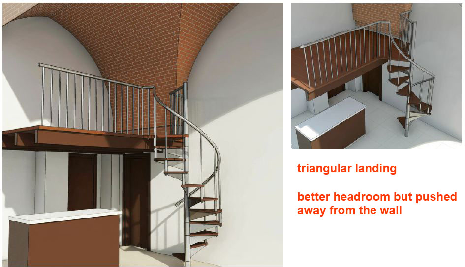
I realized that I could copy-paste these elements to “the same place”, an option which always confuses beginners, but is perfect for this situation.  Take each segment of this second copy and swap in a different profile.  Very quickly you can create the glass balustrade and tubular handrail following the same, twisting path as the strings.  Now combine a quick render with a shaded view and do a bit of cleaning up in Photoshop to disguise the imperfections.  


This image was placed on a sheet as a jpeg, along with various live views of the model, and shared with the client and structural engineer.  First iteration.  


Coming back in the new year, we had some feedback.  The strings had to be more substantial and we needed to smooth out the transitions where the runs meet the landings.  This meant resorting to point world after all.  Maybe I could use the swept blends as a guide, picking along one edge to create a 3d spline that would host profiles.


That’s one approach. But I got more control by creating profiles with a built-in offset parameter.  These could be aligned to my 2d setting-out curves and inherit vertical offsets from the swept blends ... all except the “transition” profile which was raised a little to force that smooth transition.  Then you create a single loft, instead of 4 separate swept blends which share a profile where they meet each other.


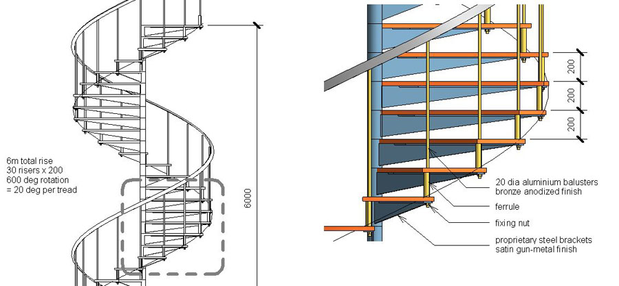
When I talk about “profiles” in a Point World context, I mean Generic Model families with a closed loop of model lines.  In this case they are drawn on a vertical work plane, with reference planes and labelled dimensions to create type and instance parameters in the usual way.  The width and height of the profile are type parameters.  The offset needs to be varied for each instance.  The notch on this profile is to allow for a soffit, most likely a stretch-fabric ceiling.


Let’s wrap this up.  Lots more work went into refining the design, especially the various junctions with floor slabs at each level.  I was using short enscape video clips to communicate the design as it developed … several clips per day.  Eventually I was asked to model the underlying steelwork to guide the structural engineer/ specialist fabricator … another interesting challenge. 


PART TWO

We’re in lockdown now, and an old friend contacted me with a “scan-to-bim” problem.  Turned out to be a stair handrail with a difficult geometry. “Aha” think I, “an opportunity to build on that work I did before, starting with some drafting in a section view (masking regions).

The first bit of String I built could have been done with swept blends.  Actually I think I had forgotten that’s what I did before, so I went straight for point world.  Just as well, because there are some portions that really need to be done as lofted forms defined by 4 or 5 profiles.


The profile is a Generic Model family, similar to the one I used before, with a somewhat fancier shape on top.  It may be that we should take a notch out of this profile where it fits over the edge of the floor slab.  Easy enough to do by editing the family and reloading.   


The string is an in-place Mass family.  I gave it an instance Material parameter so it could become red to stand out against the point cloud.  The next portion to model is quite a complex curve in 2 dimensions, formed from 5 profiles.  Each portion is sharing one profile the next piece the whole serpentine form.  So far, all the shapes have been roughed out.  There will need to be some fine tuning later on to smooth out the transitions and adjust more closely to the point cloud.


To figure out the bend where one storey meets the next. I copied the in-place family up to the next level. Changing the colour of the second copy to yellow, it is possible to turn the head of the "red serpent", up-and-around to bite the tale of the yellow one.  It seems that the floor-to-floor distance varies quite a bit, so once a typical floor is completely modelled it may be necessary to make adjustments for subsequent levels.


Now for the metal balustrade panels. The easiest one is going to be the straight portion along the landing, so let’s start with that. There is an “H” shaped extrusion, modeled directly in the host family. Next an “S-shape” created as a nested family and arrayed across the centre.  At the ends, two more nested families.  Top and bottom, in the middle, two copies of a circle family.  Nothing parametric in any of this, it would be easy enough to add some parametric capability should that seem helpful, but for now I don’t see the point.


This whole thing is going to be passed on for further development.  I just wanted to do enough to point the way.  The last piece of the puzzle in terms of tackling typical situations is a corner panel.  This is quite tricky, but can be done by setting up a diagonal reference plane to host one side. This is a loadable family and my approach is to repeatedly “have a go” ... then reload and check ... “have another go” … closer and closer.  


It requires a sharp eye and the ability to visualize 3 dimensional relationships, but can you really expect to “do BIM” without those skills?  

So there it is.  Something different after a year "slaving away" on Project Notre Dame.  I enjoyed myself.  Model in place.  You can go for weeks without using it, but sometimes it's the only way.

This "starter file" contains 3 in place mass families (in need of further refinement) There are two Generic Model "profiles" and three "rail panels". The corner panel is only half-done and there are another 3 or 4 very tricky panels to be attempted.  Good luck :)


Sunday, March 4, 2012

HELIX TAKE 2

It began as one of those little jobs for a friend of a friend.  Enhance a small studio apartment with a deck over the kitchen accessed via a spiral stair, working from a couple of photos and a thumbnail sketch.  An ideal chance to try out my adaptive family thought I.


The basic situation is as shown above, which I knocked up quickly enough.  The apartment is quite interesting in that it has a vaulted ceiling.  For this exercise it was simplest to make this as a solid block cut through in 2 directions.  In practice this was modelled in-place as an extrusion cut by a void at right angles.  You can copy-paste the shape of the arch from the extrusion sketch to the void sketch so they match.


Once I remembered how it worked, my adaptive family proved very useful.  The ease with which you can vary the height, radius, angle of revolution, no of risers etc is ideal for exploring design options on the fly.  Here you can see a comparison between 12 & 13 risers to reach a deck set at 2400. (the last riser is the deck itself)


It took me a while though to recall what I had done.  The tread assembly is a generic model embedded in a curtain panel.  The curtain panels themselves are loaded into a helical divided surface.  You have parameters to control the number of divisions and the angle of turn.  One edge of each panel is always vertical.  This represents the central pole of the staircase.  So the trick is to lock the embedded tread to this vertical side so that it will always remain true while the other relationships are varied.


Within the tread component, the vertical baluster with its nut at the end is again a nested component.  The height is controlled by a linked parameter.  There is also a spacer, between the treads, basically a tube slotted over the baluster.  Perhaps I should have made this inside the baluster component, but that would have meant at least 2 more linked parameters, and I was too impatient, so I modelled it directly in the tread family.  As a result it tends to drift off centre.


How do you lock a circular extrusion to a nested family ?  This seemed like an interesting challenge, so first I created reference plains controlled by a "baluster offset" parameter and locked the baluster to these.  Easy.  Then I found that if you create a circle from two semicircles, you can also lock these in place.  Have you noticed that Revit often makes circles in two pieces ?  Perhaps this is why.


I had also forgotten that there are separate controls for the handrail radius and the tread angle which you have to fine tune once you have set up your basic configuration.  I could have hardwired these relationships into the family, but I opted for manual control which means you can tweak things visually to line them up.  One of the frustrations of Revit's system tools for stairs and railings is the way that relationships are automatically calculated.  It's great when it works, but sometimes it would be nice to select an individual baluster and nudge it to the left a bit.


Getting back to the design problem itself, I learnt some interesting stuff about spiral stairs.  The solution I inherited had a square landing, which has certain advantages, but makes for tight headroom.  A bit of web research revealed that many of the spiral stair kits use triangular landings.  Again my adaptive family proved very useful for quickly comparing these 2 solutions.  You get better headroom, but the stair is pushed further into the room.


To understand this better I took a break from 3D and produced some simple diagrams in a drafting view. 


BIM is great, but we shouldn't forget that orthographic projection is also a very powerful tool, and sometimes a simpe abstract diagram is more effective than dozens of photorealistic images.


So a weekend's work produced two solutions to the problem, all nicely presented in both orthographic and glorious 3D.


The relative merits of triangle and square were clearly illustrated.


Personally I was leaning towards the triangle.


Turns out I had misunderstood the intention completely. The stair was supposed to go on the other side. But that was OK. Took me about an hour to make the change, including some rendering. and the inevitable adjustments to annotations when you reverse a section.


Incidentally, there's an image in there that I'm quite proud of.  It involved blending three jpegs ( 2 renders and one shaded)  The timber deck is switch off for one of the renders, and set to ghosted in the shaded view.  All 3 views contribute to achieving the right balance of transparency in the final image.


So apologies for the break in transmission.  I went on leave and have been swamped since I got back.  Hopefully I can resume regular posting now.  By way of compensation here is a link to my adaptive spiral stair. 

adaptive spiral stair.rvt

Have fun breaking it & let me know how you get on.

Thursday, January 12, 2012

UPSTAIRS DOWNSTAIRS

So last weekend I was playing on the stairs again.  This time I wanted to extend my use of the system stair tool.  No fancy conceptual massing tricks allowed.  So the obvious place to start was the spiral stair that I did a couple of posts back.  It turned out that I could create something very similar.  Slightly less control over the shape of tread, but much easier to place 2 balusters per tread, which is more realistic in terms of safety, regulations etc.


The support brackets are of course modelled as railings by creating a customised baluster family.  The stair therefore has two railings, one set to two balusters per tread, the other to one.  I will return to my adaptive stair shortly and demonstrate its ability to offer much more variety in tread design.  In the system tool you only have a single riser line to define the shape of the tread, but in my adaptive family you can basically model any shape of tread you like.


So the next little exercise was to explore different tread shapes using the system stair tool.  I made an elliptical stair and gave it treads with an "S curve".  This is quite straighforward but you need to set your geometry out carefully.  I drafted it first using detail lines, then traced over with the pick option.  The second stair is even simpler to make, but an interesting exercise all the same.  The bottom few risers are splayed, and the boundary on one side has to step and splay.


This made me think of Michelangelo's famous stair in the lobby to the Laurentian library.  I took this step by step (to coin a phrase) starting with a straight flight and progressively modifying it.  This is often a good approach so that when you inevitably receive the "can't make monolithic stair" message, you can go back to the previous stage and try again.


Eventually I was able to model something fairly convincing and then I just had to quickly rough out the tall square room that surrounds it.  I will do another post on this once I have developed it further.  Had fun with the balustrade too, all done with the normal railings tool, 2 different custom balusters, (one set to be a post at beginnings and ends) and one custom handrail profile (the bottom one is rectangular)


Just to polish off the weekend I decided to try making an ampitheatre.  Looking through my archive I came across the Theatre of Marcellus, also in Rome.  This turned into a fascinating exercise in stairs and radial arrays.  I simplified the geometry a bit so as to make the most of the array tool.  Worked like a treat.  I love the way that arrays in Revit remain "alive" so you can adjust your design as it develops. 


There are 4 or 5 different radial arrays to make up the seating and the access stairs that fit between the wedges.  For each one you keep adjusting the radius and the number of elements. Also by tabbing in to a single element and editing that group, you can adjust the instance properties of that stair, (where it starts & finishes, desired number of risers)  This was a very powerful way for me to explore the way a Roman theatre works. 


Again the surrounding structure is a possible future post, but you can get a glimpse of the way this is also largely composed of a series of live radial arrays that allow you to adjust the spacing and size of archways, column arrays etc until you are happy with the proportions and relationships. Parametric modelling at its best and all very basic Revit stuff that's been hardwired into the programme since forever.


Lest you think I am giving the stair tool to easy a ride let me finish with some grumbles.  We all know that monolithic stairs don't work properly.  They don't join to floor slabs (which is an absolute paint in the posterior) and if you want curved risers, be careful not to curve too far or they will start to cut into each other.  As for sketch mode.  It is very clever, but sometimes it just does its own thing, especially when you have a blue "run" in there.  Intermediate risers don't need to be cleaned up, which is a time saver, but make sure you clean up all the corners.

Monday, January 2, 2012

ADAPTIVE SPIRAL STAIRS

I was looking through Zach Kron's parametric patterns series, which is still  available on his Buildz website, and well worth a look if you missed it.  The  INCREMENT SPIRAL caught my eye and I started wondering "how would I convert this into a fully parametric spiral stair"


I took the family that Zach created: just a spiral line, with parameters for height, radius, rotation angle.  (You can vary the top and bottom radius separately to make a cone, but I just wanted a cylinder.)  The goal was to make a spiral surface, divide it, then populate it with curtain panel families that emulate stair treads.  The divided surface gives you a neat way to vary the number of vertical divisions.


My first attempt at a surface turned out to be a DNA style double helix.  Then I realised I could get what I wanted using the spiral plus a simple vertical line.  The heights of both are linked to  the same parameter.  I divided the surface and created a parameter called "no of risers"


Tried out a curtain pattern family with a cylinder on one edge.  Changed the panel rotation angle to get this edge in the right place.  Then replaced the cylinder with a triangle. The challenge now was to get this to sit up into the horizontal plane.


Curtain pattern families are designed to lie in the plane of a curved or twisted surface.  I needed to push one corner of my tread up, so I hosted a point on a point, gave it an offset value.and linked this to a parameter called "riser height".  Withing  the stair family, this can be tied to a formula that divides the total height by the number of risers.


So far so good and I was getting excited.  But if you look carefully they're not quite level.  I spent  some time working out trigonometric formulae, which was fun, but in the end I decided that there had to be a better way.  I had a nice family with lots of instance parameters so I could copy it around and explore lots of different sizes and shapes.  But the fact remains that each stair is made out of a series of identical components. 


So why was I fighting against the curtain panel geometry all the time trying to keep all the bits aligned to horizontal and vertical when I flex the family and the pitch of the spiral changes ?


Why not make the whole tread assembly as a nested component and simply align it with the vertical line ? (ie the post in the centre of the stair)  So I went back to an old-fashioned generic model template and made lots of extrusions.  I had to have parameter that I could link back to the host family (riser height, radius, angle etc) But at least now it was much easier to offset the baluster in from the edge of the tread and to be confident that everything would stay in the horizontal and vertical plane. 


This family was then nested into a 3 pick adaptive component.  Reporting parameters record the distance between points so as to control the riser height and radius.  So when I place the adaptive component in a curtain panel family it will automatically have the right size and alighment (pick, pick, pick)


It worked a treat, and the rest was down to designing my tread assembly.  Because curtain panels & adaptive components are shared families by default, I could just open the adaptive component directly from the project.


To prove that the result is truly orthogonal I set up some dummy construction details.  Everything dimensions very nicely

Being shared families you can select individual treads and isolate them in a view, over-ride by instance, etc.  Not sure I would use these stair families directly in a big project.  Puts a bit of a load on the processor.  But for exploring the geometry of a spiral stair it's great.  You can play with rotation angles and radii, go past 360 degrees, change the number of risers.


Once you have the configuration you want, it's possible to make a reasonable version using the Revit stair tool.  Use that in the main model, then maybe have a separate detailing file where you show the full design intent using this kind of family.  Gives you a much finer level of control than the system family tool. 


Closing with an image as usual.  Rendered and shaded views combined in Photoshop.  One extra little trick here.  Have two layers, one sharp and one blurred, then use a soft mask to fade from sharp in the midldle to blurred at the edges.  Give the illusion of depth of field