Monday, June 17, 2013

SPIKEY STUFF

SPIKEY STUFF

I posted about this way back.  

http://grevity.blogspot.ae/2012/03/more-bermuda-triangles.html

http://grevity.blogspot.ae/2012/03/drawing-curtain.html

Spikey geometry is generally easier to make in sketchup than directly in conceptual massing.  If anyone has the answer to doing it in Revit, please share, because I have failed.  You can go so far, then you get stuck.  Revit massing loves nurbs surfaces & curvy blends.  Sketchup can't do that, has to fake curves with a smoothing algorithm, because what it really loves are triangles.  It makes meshes.

Revit topography is a mesh, but just about everything else is solid geometry.  The interesting thing is that it can take a Sketchup mesh & convert it into a solid ... within limits.  For example, make an extrusion in Sketchup.  Draw a couple of diagonals on faces. Push & pull a bit.  Save.  Now open Revit.  Make an in-place mass (or an external mass family)  Import the skp file into the mass.  Finish mass.  Make mass floors.  It works.


But if you carry on playing around, pushing & pulling, triangulating & twisting: at some point it will break.  Then you get the dreaded message as you finish the mass: "... contains only mesh geometry ... can't be used to compute Mass Floors ..."  End of story.


A year ago I failed to find a way around this. Then I was thinking about some work that Jerome Buckwell & Liam Carey presented in Auckland.  They have been exploring workflows between Sketchup & Revit for concept design with considerable success.  I hope they will forgive me for including a low-res snippet from their presentation here.  It's a bit different from what I was attempting, but it got me to thinking.


If you load the Sketchup file as a link, you can keep both applications open.  Make a few changes in skp, save, reload in Revit.  If no error, carry on.  If error, backtrack & try again.


Bear in mind that my skp skills vanished about a decade ago. But gradually I found that I was evading the error message as I cycled through the process repeatedly


Just to demonstrate that Revit converts the mesh into a true solid I changed the cut pattern of the material to solid red.  Section box cuts through just as if it were standard Revit geometry.


Using this method I managed to develop quite a complex form while keeping mass floors alive.  It would be better if I had some clear rules as to what causes the "can't compute" error.  But for the meantime the "baby steps cycle" provides a workaround.


Thursday, June 13, 2013

MORE PANCAKE PEOPLE

I came across the comment below yesterday on Mark Cronin's blog   It seemed quite appropriate.  It's easy to get carried away with being "clever" & pushing the boundaries. but ultimately the success of BIM hinges on what hundreds of thousands of ordinary guys & gals can do with it out there in the construction industry.


One thing that experienced users with a public presence can do is to create better content and make it freely available.  So in this spirit, I return to the world of entourage.  If you go to my post FLAT PEOPLE & scroll down to the end, you will see that I promised to make another 15 ... IF 2 of my readers made a collection of their own available.  Exactly 2 generous souls responded to this challenge.  You can find their links under comments, and expand your entourage options with two excellent downloads.


I set about making my next batch by asking a colleague to export some sketchup people to CAD, as pickable outlines.  This kind of worked, but sadly "TAB-pick" failed.  I was faced with a rather tedious session of mouse clicking.  I could have just thrown sketchup files into Revit families, but this makes the changing of materials a bit more cumbersome and sometimes impossible.  Better quality Pancake People means native Revit geometry, so I manned up and set myself to picking.


Every cloud has a silver lining.  You have to think of something while doing a repetitive task, and I found myself reflecting on what makes for a good Entourage object.  It was obvious that different people had been involved in the original tracing exercise.  It may seem strange to talk about style & panache when referring to tracing an outline using a mouse to create short line segments, but as I proceeded, I found myself looking for figures that had been traced with a certain freedom & economy of means.  It's more effective to vary the line length and sometimes to exaggerate the changes in direction slightly to emphasise folds in cloth (for example).


Also I prefer to have my people standing firmly on the ground.  Some of the figures out there look fine in perspective view, but pretty stupid in elevation.  Perhaps this is because Sketchup doesn't feature true orthographic (one of the reasons it's not really BIM)  Then I get to thinking, "why are we taking this cardboard modelling software as the standard to aim for when it comes to people & trees & furniture ?"   There is a reason.   It's much easier to find good looking objects of these categories if you live in Skup-World.  But that doesn't mean we have to copy mindlessly.  Rise to the challenge & think about what you are doing.


Soon enough I had my first 9 persons.  Then I realised I was seriously short of Arabic people.  Time to exit Skup-Copy mode and trace directly from images.  This was another eye-opener.  If you grew up drawing freehand, as I did, you know that when it comes to people, it's all in  the hands & faces.  Mindlessly tracing hands & faces from photographs is a recipe for disaster.  You have to have some experience, and you need to stop and look at the end product and make some critical adjustments based on what your eyes tell you.  This is where the shape arrows on a Revit extrusion come in really handy.  You can make tiny adjustments to the lips & nose working directly on the extrusion.  Tweak, assess, tweak, assess.  Am I being silly ?  It's only a stylised person to throw around your project to give scale.  Oh really ?  Not to me.  We design by creating images that catch the vision that is in our imagination.  Stylisation & abstraction are thousands of years old.  For most people the effect may be subconscious, but we live in a world of visual imagery, and small details count.


Anyway I went on to create 6 entourage objects based on people wearing the national dress of the Gulf Region where I live & work.  I'm not claiming them as great works of art, but I was focussing on the kind of issues I would have been thinking about if I had been drawing with a pencil.  This brings me to my final point.  It's useful to think about tips & tricks for Revit and it's good to extend the art of the possible BUT we should also strive to treat Revit like a pencil.  Just pick it up, let it become one with your hand, eye & brain, thinking about the vision you are trying to capture.  Let the tools become transparent.  Create.

NEW COLLECTION

Oh & if anyone else wants to contribute ... that would be nice!

Wednesday, June 5, 2013

TUSCAN RIG

I'm not sure if it's jetlag or severe OCD, but I woke at the crack of dawn this morning with Tuscan columns & rectangular scalable rigs on my mind.  Let's be generous and call it a Eureka moment.  Not sure why this didn't occur to me earlier, but it is possible to use a rectangular rig to solve the scalable Tuscan dilemma.

New family - Generic Model Adaptive.  Make a rectangular rig in an elevation view.  Or just download this starter file . . .                  Rectangular Rig


The rig is set up in front elevation, so bring in a suitable jpeg and scale it to an appropriate size.  Mine happens to be six metres high and I set the width of the rig to 750, which seemed to be about right.  The next part is a bit tedious, but I had it all done by breakfast time.  Actually it's just 6.15 am as I type these words and I'm expecting the alarm to go off at any moment.

Set 3d snapping on and chain off.  Now you can created lots and lots of horizontal "rungs".  I ended up with around 25 or 26.  With a bit of practice you can draw these so that they snap to horizontal (most of the time) but don't worry if you get that "slightly out of alignment" message.  They don't actually have to be horizontal for the method to work, although it does give us an unexpected bonus later on as you will see.  The alarm is getting annoying so I will have to finish this off later.


2 fried eggs, a shave & a mad dash down Emirates Highway.  I'm in the office now and it's only 7.30 so let's continue.  Once you have some rungs in place you can start hanging splines on them.  Some of them can be drawn directly, the straight bits might be better created by selecting 2 points and doing a "spline through points".  The hardest parts to do are the straight segments with a bit of a curve on the end.  Splines are very interactive.  Push down on one part of the curve and another part will shoot up.  With a few extra points and a bit of practice you can get pretty close.


After I had done most of the capital I decided to test it out.  Just selected the spline and did a "create form"  The result is a surface and it looks pretty good to me, so on we go.

Actually I was past half way by this stage.  ie Most of the complexity in a tuscan column resides in the capital.  By the way you may notice that I did a "duplicate view" so that I had a front elevation without the jpeg.  This makes it easier to select points & see what you are doing.  (I'm still using 2013 by the way)  To complete the profile for the revolve you need to draw reference lines on top of reference lines.  This is always trick.  I wish we had subcategories of reference lines so I could have 2 types with different colours.  You can always use the sunglasses & do a temporary hide of the rig.  Anyway next thing you know I have a Tuscan column.  Looks pretty good, except for the seam.  That's one drawback with the conceptual massing revolves, they always come in 2 halves.  That's a real shame.


Took it into a project and the elevation view looks fine.  None of the artefacts we got with the "scale by spline" in vanilla Revit.  And because I took the time to get the ref lines horizontal I can get a dimension chain to pick them up.  Just do a callout and up the scale to 1:10 and we have all the dimensions my mould maker might need.


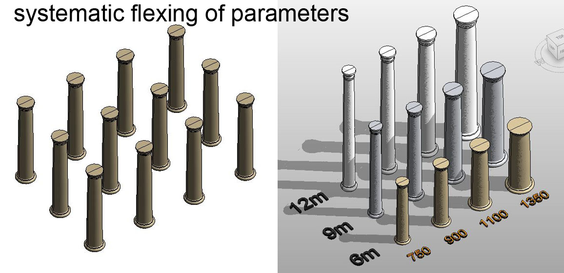
So the next step was to lay out a whole array of these things, make sure the parameters for Height & Width (actually the Width is more like a radius, it's the width of the rectangular rig, which is actually a bit more than the radius at the base of the column)  then we can vary the size of this array in a systematic manner.  I'm pretty chuffed with this result, BUT ... let's not get too carried away.


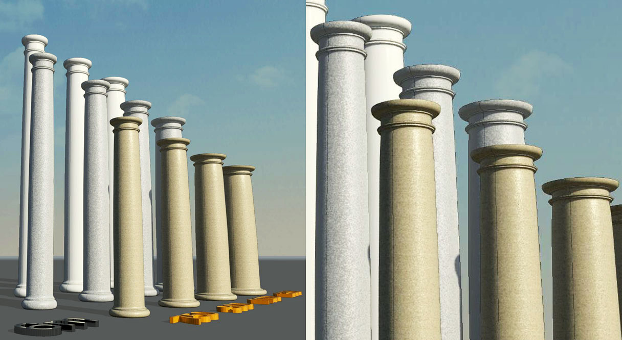
I decided to do a camera view.  Now this is where I start moaning about why we can't navigate through Revit in perspective.  Yeah, yeah, yeah ... But it is clear that errors of proportion are much more obvious in a camera shot.  Now all the columns I would be happy to use in real life, (the ones that are not ridiculously thin or disgustingly fat) are pretty good, but at the extreme ends of the scale the mouldings look wrong.  Seems to me that we should probably be making this column in 3 parts so that the width factor for base & capital can be controlled independently of the width factor for the shaft.


That will have to be for another day because it's 5 to 8 now and work beckons.  I will aim to tidy up this post at lunch time and toss it out there before leaving tonight, because tomorrow is an islamic holiday & our weekend is friday/saturday so ... LONG WEEKEND COMING.