Divide & Repeat is a new Revit 2013 feature in the Conceptual Design Environment. I got around to trying this one out last weekend. Most of what I did could have been handled using a divided surface and nesting components into a curtain panel by pattern, but the new method is more direct and easier to use.

You can draw a circle, divide it, and control the number of nodes with a parameter. Add a radius parameter. Then repeat on a second level.

Attach a simple adaptive component to two of the points and press the Repeat button. You got a ring of columns. On top of the columns I built a variable dome made from three circles whose sizes can be independently varied. The middle circle is centred between the other two as the height is varied. Allows for all kinds of shapes from onions to gherkins.

The adpative column uses a circular mass profile. New mass family. Draw a circle, turn the radius into a real dimension, label it, load it into another mass. Now it's available as a profile to make things out of and it's easily locked in place.

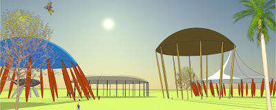
Couldn't resist playing with the new visual styles features. Realistic view with sky background & RPC content. Thanks to Luke for pointing out that you can see the sun if you look in the right direction. I had this eerie feeling that I was in a Rupert Bear world from 1960 ... something about the colours I think.
If you connect more than one object to your arrays of nodes, Revit will try to interpret this as the beginning of a pattern. So when you press the repeat button be prepared for surprise effects as the programme tries to read your mind. But meanwhile I was busy doing a couple of roof-by-face experiments.

Wasn't too hard to get a series of triangles going, and suddenly I was in 1960 again, but this time at the Rome Olympics where Mr Nervi did his thing and produced what we all thought were incredibly free-form organic structures at the time.

As I was doing this I had just done my exploration of Parts, and was considering calling it "a man of many parts" ... hence the quote attached to a completely irrelevant image of a chinese hat roof made of clay tiles.

Interlude where I played with images and refreshed my memory of the works of Pier Luigi Nervi. Lots of Sport & Bridges with the odd church thrown in for good luck.

So after a bit more playing with my bulging columns I decided to try making a Y shaped support a la Palazzetto dello Sport. Has to be adaptive of course, based on 3 points. I linked them together in a rig, with a triangle to form a plane and a parameter to vary the position of the fork.

Loading this in as lines and repeating it everything was fine.

So I fleshed it out with more circular profiles hosted on points. Hosted the circles while the points were away from the end, then pushed them out to the end using the normalised curve parameter.

So I had a highly parametric family, (roughly analogous to Nervi's dome on Y supports) which could be used to explore variations in the number of supports, curvature of the dome, etc. In short an "early design tool"

Once you've made one, further iterations become progressively easier. Triangular supports for example, and divided surface domes. I ran out of time at this point, having barely scratched the surface. There is the beginnings of a kit of parts here that could be fitted together & reused in all kinds of ways.

Had to end with another "realistic" shot, complete with Dwayne at his usual moody best. Rupert seems to have sneaked back in as well, and check out the free entourage I downloaded from a link that Luke Johnson shared (see post) One of the ladies is looking mighty suspiciously at Dwayne ... but really, can you blame her ?


You can draw a circle, divide it, and control the number of nodes with a parameter. Add a radius parameter. Then repeat on a second level.

Attach a simple adaptive component to two of the points and press the Repeat button. You got a ring of columns. On top of the columns I built a variable dome made from three circles whose sizes can be independently varied. The middle circle is centred between the other two as the height is varied. Allows for all kinds of shapes from onions to gherkins.

The adpative column uses a circular mass profile. New mass family. Draw a circle, turn the radius into a real dimension, label it, load it into another mass. Now it's available as a profile to make things out of and it's easily locked in place.

Couldn't resist playing with the new visual styles features. Realistic view with sky background & RPC content. Thanks to Luke for pointing out that you can see the sun if you look in the right direction. I had this eerie feeling that I was in a Rupert Bear world from 1960 ... something about the colours I think.

If you connect more than one object to your arrays of nodes, Revit will try to interpret this as the beginning of a pattern. So when you press the repeat button be prepared for surprise effects as the programme tries to read your mind. But meanwhile I was busy doing a couple of roof-by-face experiments.

Wasn't too hard to get a series of triangles going, and suddenly I was in 1960 again, but this time at the Rome Olympics where Mr Nervi did his thing and produced what we all thought were incredibly free-form organic structures at the time.

As I was doing this I had just done my exploration of Parts, and was considering calling it "a man of many parts" ... hence the quote attached to a completely irrelevant image of a chinese hat roof made of clay tiles.

Interlude where I played with images and refreshed my memory of the works of Pier Luigi Nervi. Lots of Sport & Bridges with the odd church thrown in for good luck.

So after a bit more playing with my bulging columns I decided to try making a Y shaped support a la Palazzetto dello Sport. Has to be adaptive of course, based on 3 points. I linked them together in a rig, with a triangle to form a plane and a parameter to vary the position of the fork.

Loading this in as lines and repeating it everything was fine.

So I fleshed it out with more circular profiles hosted on points. Hosted the circles while the points were away from the end, then pushed them out to the end using the normalised curve parameter.

So I had a highly parametric family, (roughly analogous to Nervi's dome on Y supports) which could be used to explore variations in the number of supports, curvature of the dome, etc. In short an "early design tool"

Once you've made one, further iterations become progressively easier. Triangular supports for example, and divided surface domes. I ran out of time at this point, having barely scratched the surface. There is the beginnings of a kit of parts here that could be fitted together & reused in all kinds of ways.

Had to end with another "realistic" shot, complete with Dwayne at his usual moody best. Rupert seems to have sneaked back in as well, and check out the free entourage I downloaded from a link that Luke Johnson shared (see post) One of the ladies is looking mighty suspiciously at Dwayne ... but really, can you blame her ?


