There's a half-finished post about my work on Project Soane from a couple of weeks ago that I may come back to, but for now let me skip ahead to what I've been working on this weekend.
I've been getting to grips with the interior layout of the Bank of England. Just broad brush stuff: what was there when Soane was first appointed and how he renovated and expanded it over a period of 40 years or so.

Then I started to home in on the series of banking halls around the Rotunda that he renovated in two major phases. This work is partly informed by some old photos taken by Frank Yerbury shortly before most of the bank was demolished to make way for the current version. These were on a DVD that I bought at the Bank Museum in early August. Some of these spaces go by different names based on evolving usage. I am using the names on these old photos which I find relatively easy to remember.

The photos are very useful because the drawings from Soane's office show the design in development and sometimes present conflicting information. I have been exploring this series of spaces as variations on a common theme. All of them have central domes buttressed by 4 vaulted bays and 4 smaller spaces in the corners. Like Soane I started with the Stock Office, which has been renovated to house the current museum. This was fitted into an existing rectangular space to replace a dilapidated existing hall. He chose masonry vaults and domes to avoid the problems associated with the previous timber roof structures.

These halls were built, one by one, within existing shells, so I decided to model them first as Generic Model families: simple, quick massing studies to act as a guide to later work. I wanted to resolve the major issues of scale and alignment before investing too much effort in detail. There are connections between the rooms that need to be lined up and interesting relationships between the various roof levels as they fit together like a jigsaw puzzle with interlocking light wells

I haven't done pendentives before in Revit. Turns out they are quite straightforward. Basically we are looking at a device for making the transition from square to circle: taking a dome and bringing it down onto 4 supporting columns. There always has to be buttressing to deal with the lateral thrust, but the main wait is coming down on the corner columns. It's clear from the drawings that the roofs are flat, so I made my pendentives from a box cut by a revolve.

In Soane's domes the centre of the dome is often well below the springing point leading to his characteristic shallow arches meeting the columns at an angle. That's how the Stock Office works.

But sometimes he has sufficient height to allow a full semicircle with the dome flowing down smoothly into the columns. The colonial office is a good example.

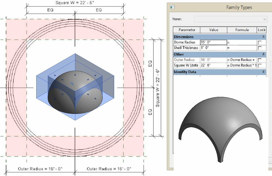
So let's take a closer look at pendentive geometry. I made a basic parametric family to illustrate this. We start off with a revolve that creates a hemispherical shell. Parameters for inside radius and shell thickness. Formula to add these together for the outer radius.

Now set up a reference planes to define a square. We're going to use these to control a void in the form of a square donut. This will cut away the sides of the dome creating 4 arches and 4 point supports.

To complete the picture we need upper and lower cutting planes that can also be varied parametrically. I've set this whole thing up so that the cutting planes are controlled as fractions of the dome radius. That way, when you type in a new radius the whole thing scales up while maintaining its basic shape.

The end result is a family with 5 instance parameters that can change its size, an vary between a full hemisphere and one of Soane's relatively flat "canopy domes". So much for basic dome theory.
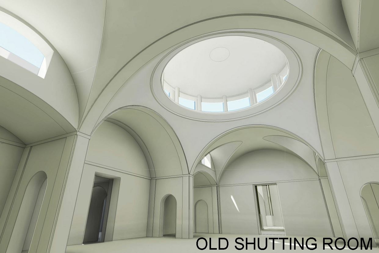
A set of pendentives can be used to support a simple dome, or a dome on a drum, or lightweight lantern which is what we see at the Bank of England. In the stock office he uses decorative steel brackets to support the lantern roof, shallow arches at the sides, and groin vaults at the ends which allow for steel framed clerestory windows above the corner bays. These corner bay receive additional daylight from circular holes cut through the ceiling.

To the left you can see a doorway that leads through to the Old Shutting Room which was the next space that Soane rebuilt, once again fitted within and existing shell of perimeter walls. You can see from the way that Soane places 4 columns around each of the corner bays that he is not relying on these older walls to carry any load. Everything can be taken down to new foundations within the interior.

The same strategy is used in the Shutting Room. The door in front of us is the one we saw before coming from the Stock Office, while the one on the left leads to the Consols Transfer Office which is part of the extensive North-East extension that Soane built over the next few years. This has already been modelled in some detail by Russell Fuller Hill, an excellent contribution which helped me to build a simpler massing model.

You can see my take on the CTO on the left in orange. This is again a Generic Model Family, but nested within a link so it can be easily swapped out with Russell's version. That's the strategy I'm aiming towards here, a series of modules with different versions that can be loaded and unloaded depending on where your focus is and the processing power that you have available.

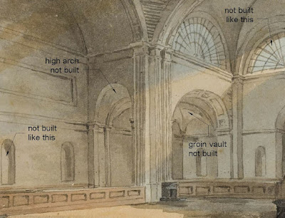
I haven't gone into as much detail as Russel. No need to duplicate his efforts, but by standing on his shoulders and with the benefit of the old photographs I think I have been able to progress our understanding of what was actually built. For example the arches that connect the side bays to the corner spaces are lower in my version. Russel had followed the majority of the drawings, but the photos suggest that Soane made a late change and one drawing (which I think is a record of progress on site) seems to confirm this.

The photos suggest that the design for the casing to the columns was also changed, simplified down to a single recess with a Greek key moulding for the capital. These are all subtle changes, but show an ever thoughtful architect reflecting on his design and making late adjustments. The lower arch in particular has practical implications in that it keeps the crown below the springing point of the arches to the corner bays so that these can have a simple arched ceiling rather than the groin vault originally envisaged.
With some reluctance I have rotated the Consols Transfer Office and the Shutting Room by 1 degree. This is to line up an axis from the rotunda, through these two spaces to the apse at the end of Lothbury Court. This also brings the CTO closer into line with Cockerell's plan which we have chosen as our common base and from which I developed my guide grid. For the moment I end up with double walls with wedge shaped cavities in some locations.

I think it's important to make the connections between the rooms fall in more or less the right places, and to maintain the most obvious axial alignments. I am intrigued by this aspect of Soane's work: how he adapted to the difficult angles he inherited and created spaces that may look slightly awkward in plan, but would have flowed quite naturally and regularly as a walked experience.
It also strikes me that the CTO does not have full columns up against the perimeter walls, like the previous two banking halls. This suggests that the walls themselves are loadbearing, which is logical enough given that this is a completely new extension. These are the kinds of insights that I believe justify the use of BIM on a historical research project of this nature. Revit makes you think like a builder.

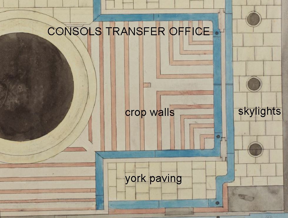
And as an ex-bricklayer, I do hope I can find time to model the construction of part of one of the roofs over these vaults and pendentives. The drawings show "crop walls" which I would have called "dwarf walls" and spanning over them "York Paving" slabs, which is basically the same material that I saw used for the floors in the reconstructed Stock Office.
Was that the final finish? What about waterproofing ? A roofscape photo shows sheet metal on a portion of flat roof around the lantern, but this could have been added later.

Oh and the three black holes at the end of the CTO in the drawing ? I'm quite sure these are skylights in the ceiling of the passage leading towards the Consols Library, which is directly behind the exterior screen wall and therefore has no windows. It was accessed via half a dozen steps at the end of the CTO.

They would have been very similar to the ones in the Stock Office, probably covered with a small octagonal lantern like the one you can see in this photo that I took from inside the museum. It's a bit washed out, but clearly visible.

I've been getting to grips with the interior layout of the Bank of England. Just broad brush stuff: what was there when Soane was first appointed and how he renovated and expanded it over a period of 40 years or so.

Then I started to home in on the series of banking halls around the Rotunda that he renovated in two major phases. This work is partly informed by some old photos taken by Frank Yerbury shortly before most of the bank was demolished to make way for the current version. These were on a DVD that I bought at the Bank Museum in early August. Some of these spaces go by different names based on evolving usage. I am using the names on these old photos which I find relatively easy to remember.

The photos are very useful because the drawings from Soane's office show the design in development and sometimes present conflicting information. I have been exploring this series of spaces as variations on a common theme. All of them have central domes buttressed by 4 vaulted bays and 4 smaller spaces in the corners. Like Soane I started with the Stock Office, which has been renovated to house the current museum. This was fitted into an existing rectangular space to replace a dilapidated existing hall. He chose masonry vaults and domes to avoid the problems associated with the previous timber roof structures.

These halls were built, one by one, within existing shells, so I decided to model them first as Generic Model families: simple, quick massing studies to act as a guide to later work. I wanted to resolve the major issues of scale and alignment before investing too much effort in detail. There are connections between the rooms that need to be lined up and interesting relationships between the various roof levels as they fit together like a jigsaw puzzle with interlocking light wells

I haven't done pendentives before in Revit. Turns out they are quite straightforward. Basically we are looking at a device for making the transition from square to circle: taking a dome and bringing it down onto 4 supporting columns. There always has to be buttressing to deal with the lateral thrust, but the main wait is coming down on the corner columns. It's clear from the drawings that the roofs are flat, so I made my pendentives from a box cut by a revolve.

In Soane's domes the centre of the dome is often well below the springing point leading to his characteristic shallow arches meeting the columns at an angle. That's how the Stock Office works.

But sometimes he has sufficient height to allow a full semicircle with the dome flowing down smoothly into the columns. The colonial office is a good example.

So let's take a closer look at pendentive geometry. I made a basic parametric family to illustrate this. We start off with a revolve that creates a hemispherical shell. Parameters for inside radius and shell thickness. Formula to add these together for the outer radius.

Now set up a reference planes to define a square. We're going to use these to control a void in the form of a square donut. This will cut away the sides of the dome creating 4 arches and 4 point supports.
To complete the picture we need upper and lower cutting planes that can also be varied parametrically. I've set this whole thing up so that the cutting planes are controlled as fractions of the dome radius. That way, when you type in a new radius the whole thing scales up while maintaining its basic shape.

The end result is a family with 5 instance parameters that can change its size, an vary between a full hemisphere and one of Soane's relatively flat "canopy domes". So much for basic dome theory.
A set of pendentives can be used to support a simple dome, or a dome on a drum, or lightweight lantern which is what we see at the Bank of England. In the stock office he uses decorative steel brackets to support the lantern roof, shallow arches at the sides, and groin vaults at the ends which allow for steel framed clerestory windows above the corner bays. These corner bay receive additional daylight from circular holes cut through the ceiling.

To the left you can see a doorway that leads through to the Old Shutting Room which was the next space that Soane rebuilt, once again fitted within and existing shell of perimeter walls. You can see from the way that Soane places 4 columns around each of the corner bays that he is not relying on these older walls to carry any load. Everything can be taken down to new foundations within the interior.
The same strategy is used in the Shutting Room. The door in front of us is the one we saw before coming from the Stock Office, while the one on the left leads to the Consols Transfer Office which is part of the extensive North-East extension that Soane built over the next few years. This has already been modelled in some detail by Russell Fuller Hill, an excellent contribution which helped me to build a simpler massing model.

You can see my take on the CTO on the left in orange. This is again a Generic Model Family, but nested within a link so it can be easily swapped out with Russell's version. That's the strategy I'm aiming towards here, a series of modules with different versions that can be loaded and unloaded depending on where your focus is and the processing power that you have available.

I haven't gone into as much detail as Russel. No need to duplicate his efforts, but by standing on his shoulders and with the benefit of the old photographs I think I have been able to progress our understanding of what was actually built. For example the arches that connect the side bays to the corner spaces are lower in my version. Russel had followed the majority of the drawings, but the photos suggest that Soane made a late change and one drawing (which I think is a record of progress on site) seems to confirm this.

The photos suggest that the design for the casing to the columns was also changed, simplified down to a single recess with a Greek key moulding for the capital. These are all subtle changes, but show an ever thoughtful architect reflecting on his design and making late adjustments. The lower arch in particular has practical implications in that it keeps the crown below the springing point of the arches to the corner bays so that these can have a simple arched ceiling rather than the groin vault originally envisaged.

With some reluctance I have rotated the Consols Transfer Office and the Shutting Room by 1 degree. This is to line up an axis from the rotunda, through these two spaces to the apse at the end of Lothbury Court. This also brings the CTO closer into line with Cockerell's plan which we have chosen as our common base and from which I developed my guide grid. For the moment I end up with double walls with wedge shaped cavities in some locations.

I think it's important to make the connections between the rooms fall in more or less the right places, and to maintain the most obvious axial alignments. I am intrigued by this aspect of Soane's work: how he adapted to the difficult angles he inherited and created spaces that may look slightly awkward in plan, but would have flowed quite naturally and regularly as a walked experience.
It also strikes me that the CTO does not have full columns up against the perimeter walls, like the previous two banking halls. This suggests that the walls themselves are loadbearing, which is logical enough given that this is a completely new extension. These are the kinds of insights that I believe justify the use of BIM on a historical research project of this nature. Revit makes you think like a builder.

And as an ex-bricklayer, I do hope I can find time to model the construction of part of one of the roofs over these vaults and pendentives. The drawings show "crop walls" which I would have called "dwarf walls" and spanning over them "York Paving" slabs, which is basically the same material that I saw used for the floors in the reconstructed Stock Office.
Was that the final finish? What about waterproofing ? A roofscape photo shows sheet metal on a portion of flat roof around the lantern, but this could have been added later.
Oh and the three black holes at the end of the CTO in the drawing ? I'm quite sure these are skylights in the ceiling of the passage leading towards the Consols Library, which is directly behind the exterior screen wall and therefore has no windows. It was accessed via half a dozen steps at the end of the CTO.

They would have been very similar to the ones in the Stock Office, probably covered with a small octagonal lantern like the one you can see in this photo that I took from inside the museum. It's a bit washed out, but clearly visible.

It's really coming together, great job!!
ReplyDeleteHello,
ReplyDeleteMy name is Anthony Duncan and I am an Architecture student at Kent State University. I am currently working on a project about the original Bank of England and this has by far been the most useful and helpful site. It looks like you have developed a nice 3D model of the original bank. I was wondering if I would be able to obtain a copy of that 3D model to use for analysis and a presentation. I can use it in any software (Rhino, SketchUp, AutoCAD etc..). My email is adunca21@kent.edu Please let me know if this is possible. Thanks!
Anthony Duncan
Hello, thank you for the information. How can I use the void forms as a donut? I created two void squares but I dont get them to work as in your example. Thank you
ReplyDeletethank for the wonderful post , lots of information gained , visit us Revit Modeling in uk
ReplyDelete