When I was looking for everyday objects to model in point world (for my RTC presentation in Chicago) one of the first pieces of furniture that sprang to mind was the Space chair. A Fritz Hansen original, much copied, classic use of moulded plastic sheet.

For the longest time I couldn't figure out how to make it. I kept trying to see the form as a series of profiles hosted on a spline, but that turned out to be really clumsy.

Then one day the penny dropped. Actually you don't need Point World. The underlying form is a blend. It's like one of those thached roofs that are round at both ends with a straight ridge in the middle.

Flip that upside down, at an angle. Make a similar void, slightler smaller, cut away and you've got it.

Well it needs to be trimmed around the edges of course, but that shouldn't be too hard. So I started with a profile.

The swept blend was a wonderful thing when it was first released, then a year later it got overshadowed by Point World and I've been neglecting it ever since. First insight. You can do a swept blend with a straight line. Why bother ? Because it allows you to use loaded profiles, something that ordinary blends don't accommodate (perhaps they should)

Using a straight line as the path for a swept blend gives me lots of control, easy to adjust the length and angle. The profiles are parametric, easy to adjust their sizes and proportions. I was using a CAD download from Fritz Hansen as a guide to get the size & shape right.

My first attempt to trim the edges was awful. Second go was much better, but you can still see sharp edges when you zoom in close.

I decided that I needed a void blend. Now you can make a void extrusion with a hole in the middle, but that won't work with a blend. You can only have one closed loop at each end. No donuts allowed ... unless you leave a little sliver of a gap somewhere so that actually it's just one loop.

That's what I opted to do. Not very elegant, but it works. I leaves you with a spike of plastic sticking out sideways as if the shape had been injection moulded rather than pressed from sheet, but with care you can clip this off so that it's barely noticeable.

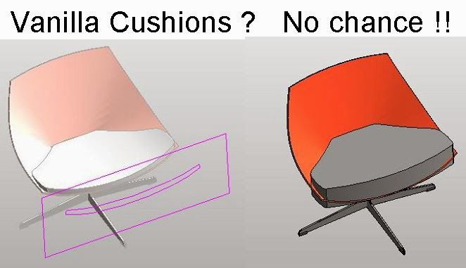
Now for the cushions. I had a quick go at making these in Vanilla also, but it was never going to work, so I'm back in point world after all. I isolated the cad object for the cushions. It's a mesh. Maybe some of you know how to convert this into a solid that will come into Revit and explode nicely. That would save time, but I've never figured that one out, so I'm going to make if from a series of profiles ... in Point World.
I decided to set up a series of reference planes that slice through a cushion. They don't actually cut it of course, but I can host splines on these planes and adjust them until they are pretty much sitting on the surface. A bit tedious, but it was an interesting exercise.

I'm using conventional 2d splines here, the kind that stay resolutely on the reference plane you put them on. So the only ref points belong to the straight lines that are used to close the loops using 3d snapping.

Use create form on the first 2 or 3 loops. Then progressively add more to create a reasonably convincing replicat of the CAD cushion.

You can easily see where your surface is proud of the original and where it dips below. Select the nearest spline, look for a node, adjust to your heart's content.

There's always going to be a flat end where your last profile sits, but you can make this very small, or you can just decide that it's not going to show up, especially if the cushions are black, which they often are.

When exporting to cad from a family, your temporary hide/isolate settings are respected, so it's easy to push this out as an SAT solid. Open this in autocad and you get a chance to round off the sharp edges.

Import SAT back into Revit and explode. Now it's free-form native geometry and you can apply a material parameter.
The base is pretty straightforward to make so I won't go into much detail. It helps to set up a ref plane with a parallel section plane when creating the extrusions for the legs and the revolves at the end where they attach to the plastic.

You might think that this results in a heavyweight family, but it's just over 1mb. I'm not going to spray hundreds of these around anyway. There are a masking regions and symbolic lines to represent the object in plan views. Interesting to note that the "free form element" for the cushions doesn't trigger a "visibility settings" button on the ribbon. Fortunately you can turn it off in plan views via the "Visibility/Graphics Overrides" in the properties dialogue. Another case of inconsistent terminology for Steve Stafford's record book.

I've turned all the 3d geometry off in orthographic views and at coarse detail level. That should handle most performance issues

For the front & side elevations I used the CAD objects kindly provided by Fritz Hansen. Just added a masking region.

Hope you found that interesting. Download the family here
.Space Chair Download

I'm going to finish with a gag reel that illustrates the follies of cleverness. More failed attempts to create the space chair using Point World gymnastics.

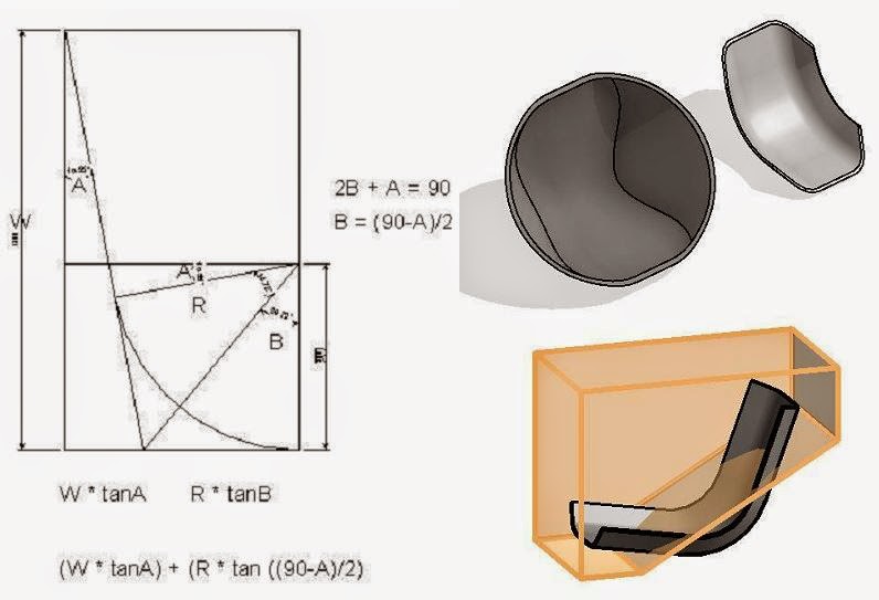
Along the way I developed the most complex trigonometric formula I have ever devised for Revit. (not saying much) But none of the results lived up to expectations. What a waste of effort.
Or maybe not. Sometimes the simple solution will only come to mind after a long & difficult search.
For the longest time I couldn't figure out how to make it. I kept trying to see the form as a series of profiles hosted on a spline, but that turned out to be really clumsy.
Then one day the penny dropped. Actually you don't need Point World. The underlying form is a blend. It's like one of those thached roofs that are round at both ends with a straight ridge in the middle.
Flip that upside down, at an angle. Make a similar void, slightler smaller, cut away and you've got it.
Well it needs to be trimmed around the edges of course, but that shouldn't be too hard. So I started with a profile.
The swept blend was a wonderful thing when it was first released, then a year later it got overshadowed by Point World and I've been neglecting it ever since. First insight. You can do a swept blend with a straight line. Why bother ? Because it allows you to use loaded profiles, something that ordinary blends don't accommodate (perhaps they should)
Using a straight line as the path for a swept blend gives me lots of control, easy to adjust the length and angle. The profiles are parametric, easy to adjust their sizes and proportions. I was using a CAD download from Fritz Hansen as a guide to get the size & shape right.
My first attempt to trim the edges was awful. Second go was much better, but you can still see sharp edges when you zoom in close.
I decided that I needed a void blend. Now you can make a void extrusion with a hole in the middle, but that won't work with a blend. You can only have one closed loop at each end. No donuts allowed ... unless you leave a little sliver of a gap somewhere so that actually it's just one loop.
That's what I opted to do. Not very elegant, but it works. I leaves you with a spike of plastic sticking out sideways as if the shape had been injection moulded rather than pressed from sheet, but with care you can clip this off so that it's barely noticeable.
Now for the cushions. I had a quick go at making these in Vanilla also, but it was never going to work, so I'm back in point world after all. I isolated the cad object for the cushions. It's a mesh. Maybe some of you know how to convert this into a solid that will come into Revit and explode nicely. That would save time, but I've never figured that one out, so I'm going to make if from a series of profiles ... in Point World.
I decided to set up a series of reference planes that slice through a cushion. They don't actually cut it of course, but I can host splines on these planes and adjust them until they are pretty much sitting on the surface. A bit tedious, but it was an interesting exercise.
I'm using conventional 2d splines here, the kind that stay resolutely on the reference plane you put them on. So the only ref points belong to the straight lines that are used to close the loops using 3d snapping.
Use create form on the first 2 or 3 loops. Then progressively add more to create a reasonably convincing replicat of the CAD cushion.
You can easily see where your surface is proud of the original and where it dips below. Select the nearest spline, look for a node, adjust to your heart's content.
There's always going to be a flat end where your last profile sits, but you can make this very small, or you can just decide that it's not going to show up, especially if the cushions are black, which they often are.
When exporting to cad from a family, your temporary hide/isolate settings are respected, so it's easy to push this out as an SAT solid. Open this in autocad and you get a chance to round off the sharp edges.
Import SAT back into Revit and explode. Now it's free-form native geometry and you can apply a material parameter.
The base is pretty straightforward to make so I won't go into much detail. It helps to set up a ref plane with a parallel section plane when creating the extrusions for the legs and the revolves at the end where they attach to the plastic.
You might think that this results in a heavyweight family, but it's just over 1mb. I'm not going to spray hundreds of these around anyway. There are a masking regions and symbolic lines to represent the object in plan views. Interesting to note that the "free form element" for the cushions doesn't trigger a "visibility settings" button on the ribbon. Fortunately you can turn it off in plan views via the "Visibility/Graphics Overrides" in the properties dialogue. Another case of inconsistent terminology for Steve Stafford's record book.
I've turned all the 3d geometry off in orthographic views and at coarse detail level. That should handle most performance issues
For the front & side elevations I used the CAD objects kindly provided by Fritz Hansen. Just added a masking region.
Hope you found that interesting. Download the family here
.Space Chair Download
I'm going to finish with a gag reel that illustrates the follies of cleverness. More failed attempts to create the space chair using Point World gymnastics.
Along the way I developed the most complex trigonometric formula I have ever devised for Revit. (not saying much) But none of the results lived up to expectations. What a waste of effort.
Or maybe not. Sometimes the simple solution will only come to mind after a long & difficult search.
Could you publish a fast video on this tutorial.
ReplyDeletethank for the wonderful post , lots of information gained , visit us Revit Modeling in uk
ReplyDeleteMultiwood furniture is highly resistant to changes in temperature and humidity. Unlike traditional wood, which expands or contracts with weather conditions, multiwood remains stable, making it ideal for coastal and humid environments.
ReplyDeleteNice articles and your information valuable and good articles thank for the sharing information mono mesh office chair
ReplyDeleteThis article highlights waiting chairs public seating for hospital comfort zones, emphasizing ergonomic design, soothing aesthetics, and durable materials to create relaxing, patient-friendly spaces that reduce stress during waiting times.
ReplyDeleteThis post provides valuable insights on waiting chairs public seating for hospital crowd management, emphasizing high-capacity layouts, durable construction, and space-efficient design to improve patient flow and reduce congestion in busy healthcare facilities.
ReplyDeleteGreat overview of waiting chairs public seating for industrial offices—highlights durability, ergonomic design, and low-maintenance features, making them ideal for functional and heavy-use workplace environments.
ReplyDeleteWaiting chairs public seating in colleges ensure comfort for students and visitors, help manage queues, and support an organized, welcoming academic environment.
ReplyDeleteWaiting chairs public seating in lounges provide comfort, promote organized seating, and create a pleasant, relaxing environment for guests during their wait.
ReplyDeletePlastic chair plastic chair manufacturers ensure durability by using high-quality materials, reinforced designs, and advanced molding techniques to withstand daily use and long-term wear.
ReplyDeleteWaiting chairs for executive offices offer stylish, comfortable, and professional seating, creating a public seating welcoming environment for visitors while complementing the office’s upscale décor.
ReplyDeleteWaiting chairs for durable public seating seating systems are built to withstand heavy use while providing comfort and stability, making them ideal for offices, institutions, and high-traffic public areas.
ReplyDeleteWaiting chair usage in institutional buildings public seating includes hospitals, schools, banks, and government offices, providing durable, comfortable, and organized seating solutions to accommodate high foot traffic and enhance visitor experience.
ReplyDeleteWaiting chair design evolution reflects shifts from public seating simple, functional seating to modern, ergonomic, and stylish designs, incorporating durable materials, modular layouts, comfortable cushions, and aesthetic finishes for public and commercial spaces.
ReplyDeleteOutdoor plastic chairs plastic chair with UV protection offer durable, fade‑resistant seating that withstands sun exposure, retains color, and provides comfortable outdoor use for gardens, patios, and events.
ReplyDeleteWaiting chair design public seating for clinics should focus on comfort, durability, and hygiene, featuring ergonomic seating, easy-to-clean surfaces, compact layout for space efficiency, and materials that withstand frequent use.
ReplyDeleteWaiting chairs for OPD public seating waiting areas should provide comfortable, durable, and easy-to-clean seating, with ergonomic support and space-efficient designs to accommodate high patient flow efficiently.
ReplyDeleteNice articles and your information valuable and good articles thanks for the sharing information Office chair cushion
ReplyDeleteNice articles and your information valuable and good articles thanks for the sharing information Cafeteria chair
ReplyDeleteNice articles and your information valuable and good articles thanks for the sharing information Chair knob parts
ReplyDeleteNice articles and your information valuable and good articles thanks for the sharing information seating support cushion
ReplyDeleteNice articles and your information valuable and good articles thanks for the sharing information ergonomic seat cushion
ReplyDeleteNice articles and your information valuable and good articles thanks for the sharing information outdoor café table materials
ReplyDeleteNice articles and your information valuable and good articles thanks for the sharing information café table for small spaces
ReplyDeleteNice articles and your information valuable and good articles thanks for the sharing information back support chair cushion
ReplyDeleteNice articles and your information valuable and good articles thanks for the sharing information space efficient furniture for cafés
ReplyDeleteNice articles and your information valuable and good articles thanks for the sharing information stylish café table for indoor seating
ReplyDeleteNice articles and your information valuable and good articles thanks for the sharing information ergonomic bar stools for indoor use
ReplyDeleteNice articles and your information valuable and good articles thanks for the sharing information stylish cafe tables for modern interiors
ReplyDeleteNice articles and your information valuable and good articles thanks for the sharing information back support pillow for office chair
ReplyDeleteNice articles and your information valuable and good articles thanks for the sharing information Affordable cafe chairs for commercial use
ReplyDeleteNice articles and your information valuable and good articles thanks for the sharing information Seat cushion for posture correction
ReplyDeleteNice articles and your information valuable and good articles thanks for the sharing information Restaurant chairs with arms
ReplyDeleteNice articles and your information valuable and good articles thanks for the sharing information Easy-maintenance plastic chair
ReplyDeleteNice articles and your information valuable and good articles thanks for the sharing information cervical pillow for overnight neck support
ReplyDeleteNice articles and your information valuable and good articles thanks for the sharing information Comfortable cafe chairs for customers
ReplyDeleteNice articles and your information valuable and good articles thanks for the sharing information modern trends in plastic chair design
ReplyDelete