Truth be told, I don't get to use massing & curtain systems a great deal in my day job. Both Revit and I have been bracketed as practical tools to be employed when projects are approaching the "nitty gritty stage". I have accepted this as a fact of life, while remaining hopeful that the advantages of the BIM approach will gradually trickle down to those guys over in the corner playing with Sketchup all day.

So it's always a pleasant surprise to get a request for help at the earliest, exploratory stages of a design study. The starting point was an abstract form that has been quickly knocked up in the aforementioned digital cardboard modelling tool. It's easy enough to import this into a massing family, go to object styles and assign a material to layers. I wanted something slightly transparent. It only works if textures were applied "bylayer": hence the yellow roofing here which failed to pick up the material from object styles.

Now you can bring this family into a project and use the "Curtain System by Face" command. I wanted 2 types of curtain system. Both of them have big mullions around the edge and no internal divisions. One is glazed & the other is solid (for the roof). This is easily set up using the type properties for Curtain Systems, Curtain Wall Mullions & Curtain Panels.

Once these were set up, I zipped around happily clicking on triangles and confirming with the "Create System" button from time to time.

In no time at all you have a form which renders up very nicely, and you can play around with visual styles to your hearts content.

Here's one that I did with a few image processing trips, (smudge stick overlay, desaturate, blurring and masking to simulate depth of field)

All joking aside, Sketchup is a great little program for knocking up triangulated surfaces like this. In fact that is all it does really. Everything else is smoke and mirrors in the software to disguise the joins between triangles. Very clever, but it's just faces. As a result you can't use the mass to generate floor faces and calculate areas & volumes. Perhaps you would be better off making the original form in AutoCAD 3D. Not quite so user-friendly, but you might just be able to convert in into a solid.

In my case I decided to build a real Revit form using the imported object as a guide. It was fiddly, but it worked. Start off by drawing a profile (closed loop of lines) in a top view. Select this and "create form" You get an extrusion. I changed the colour of the imported object to all yellow, and made the Revit form purple. Now with the view set to ghost surfaces, I can see both shapes and how they overlap.

The rest is a matter of push-pulling points and orbiting around all the time as you work. Slowly by slowly the Revit form can be adjusted to come quite close to the imported object. The main difference is that the vertical sides will tend to be twisted quadrilaterals.

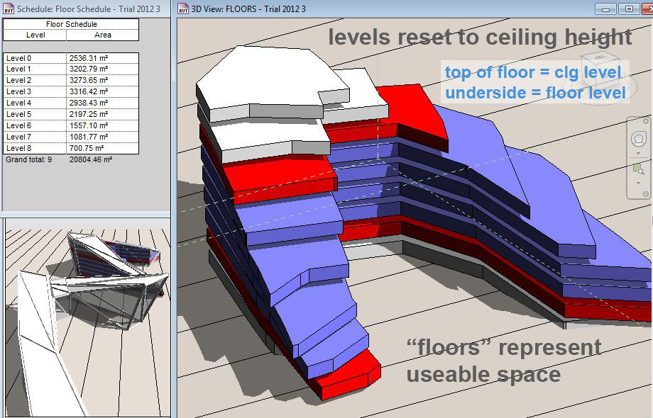
Back in the project I set up some levels, reloaded the mass family, created mass floor faces and then real floors (using floor by face)


You can schedule these floors to add up their areas, but then you realise that this is not all USEABLE space. The ceiling height tapers down to nothing in several places.

My answer to this was to move the floors up to ceiling level and make them thick enough to fill up the useable space. Just for fun I made three types of floor to represent different functional areas of the building. So now you have a diagram that represents useable space as a solid and the floor/ceiling zone as a void.

The areas have gone down because these are all now full-height, useable spaces.
This diagram sits quite nicely inside our triangulated skin, but sticks out just slightly in some places where the twisted surfaces of the Revit mass don't quite match the original triangles.
 As far as I know, there is no easy way to split the twisted face of a Revit solid into 2 triangles. You can easily add a triangular surface (which is what Sketchup does) But that remains separate from the solid mass. It can be used to make curtain systems by face, but not for making floors and calculating areas. Within the conceptual massing environment there are tools called "add profile" & "add edge". Wouldn't it be nice if there was an "add diagonal". This would allow you to start with an extrusion and gradually deform it into an irregular shape where all the faces are flat and triangular.

Actually there is another approach which is interesting, but not very helpful. You can divide the surface using a 1x1 pattern of flat triangles. At first this seemed promising, but turned out to be disappointing for several reasons. First of all the mass floors use the original twisted face and ignore the divided surface. So your floors still stick out through the skin. Also, curtain system by face selects the whole surface.

Secondly the triangles are actually two halves. This shows up when you load a component with glass and framing. It's easier to understand if you increase the number of sides to say 2x2 which will create 2 full triangles and 4 half triangles (if the surface you start with has 4 sides). In the image abover you can see lots of rectangles floating in space. These are the profiles I used to define the shape of the framing. Revit cuts off the framing of partial panels but doesn't hide the profile because this is used in the one and a half sides of framing that remain. So it shows up even if it is actually located in the part of the frame that has beeen cut off. You can use a parameter to hide the profile, but you are still left with "missing edges" to the frames.

Thirdly you can't decide which diagonal to choose, which generally makes the difference between convex and concave and affects whether the floors will stick out of the skin or not. And fourthly, the corners junctions of mullions are harder to resolve than with the curtain system by face tool.
So my preferred workflow for cladding this kind of Revit mass in giant triangular panels is to manually add triangular faces. You only need to do this for faces that are not triangular in the original mass.

You can choose which diagonal to use, and make further subdivisions at will. The corner points remain attached to the original mass so you can continue to manipulate this, reload into the project and update curtain systems. It's a workaround, but it gives you a way to model these kinds of spiky angular forms directly in Revit.
Later on you can add mullions and panels into your curtains system as shown in my final image.


So it's always a pleasant surprise to get a request for help at the earliest, exploratory stages of a design study. The starting point was an abstract form that has been quickly knocked up in the aforementioned digital cardboard modelling tool. It's easy enough to import this into a massing family, go to object styles and assign a material to layers. I wanted something slightly transparent. It only works if textures were applied "bylayer": hence the yellow roofing here which failed to pick up the material from object styles.

Now you can bring this family into a project and use the "Curtain System by Face" command. I wanted 2 types of curtain system. Both of them have big mullions around the edge and no internal divisions. One is glazed & the other is solid (for the roof). This is easily set up using the type properties for Curtain Systems, Curtain Wall Mullions & Curtain Panels.

Once these were set up, I zipped around happily clicking on triangles and confirming with the "Create System" button from time to time.

In no time at all you have a form which renders up very nicely, and you can play around with visual styles to your hearts content.

Here's one that I did with a few image processing trips, (smudge stick overlay, desaturate, blurring and masking to simulate depth of field)

All joking aside, Sketchup is a great little program for knocking up triangulated surfaces like this. In fact that is all it does really. Everything else is smoke and mirrors in the software to disguise the joins between triangles. Very clever, but it's just faces. As a result you can't use the mass to generate floor faces and calculate areas & volumes. Perhaps you would be better off making the original form in AutoCAD 3D. Not quite so user-friendly, but you might just be able to convert in into a solid.

In my case I decided to build a real Revit form using the imported object as a guide. It was fiddly, but it worked. Start off by drawing a profile (closed loop of lines) in a top view. Select this and "create form" You get an extrusion. I changed the colour of the imported object to all yellow, and made the Revit form purple. Now with the view set to ghost surfaces, I can see both shapes and how they overlap.

The rest is a matter of push-pulling points and orbiting around all the time as you work. Slowly by slowly the Revit form can be adjusted to come quite close to the imported object. The main difference is that the vertical sides will tend to be twisted quadrilaterals.

Back in the project I set up some levels, reloaded the mass family, created mass floor faces and then real floors (using floor by face)


You can schedule these floors to add up their areas, but then you realise that this is not all USEABLE space. The ceiling height tapers down to nothing in several places.

My answer to this was to move the floors up to ceiling level and make them thick enough to fill up the useable space. Just for fun I made three types of floor to represent different functional areas of the building. So now you have a diagram that represents useable space as a solid and the floor/ceiling zone as a void.
The areas have gone down because these are all now full-height, useable spaces.
This diagram sits quite nicely inside our triangulated skin, but sticks out just slightly in some places where the twisted surfaces of the Revit mass don't quite match the original triangles.

Actually there is another approach which is interesting, but not very helpful. You can divide the surface using a 1x1 pattern of flat triangles. At first this seemed promising, but turned out to be disappointing for several reasons. First of all the mass floors use the original twisted face and ignore the divided surface. So your floors still stick out through the skin. Also, curtain system by face selects the whole surface.

Secondly the triangles are actually two halves. This shows up when you load a component with glass and framing. It's easier to understand if you increase the number of sides to say 2x2 which will create 2 full triangles and 4 half triangles (if the surface you start with has 4 sides). In the image abover you can see lots of rectangles floating in space. These are the profiles I used to define the shape of the framing. Revit cuts off the framing of partial panels but doesn't hide the profile because this is used in the one and a half sides of framing that remain. So it shows up even if it is actually located in the part of the frame that has beeen cut off. You can use a parameter to hide the profile, but you are still left with "missing edges" to the frames.

Thirdly you can't decide which diagonal to choose, which generally makes the difference between convex and concave and affects whether the floors will stick out of the skin or not. And fourthly, the corners junctions of mullions are harder to resolve than with the curtain system by face tool.
So my preferred workflow for cladding this kind of Revit mass in giant triangular panels is to manually add triangular faces. You only need to do this for faces that are not triangular in the original mass.

You can choose which diagonal to use, and make further subdivisions at will. The corner points remain attached to the original mass so you can continue to manipulate this, reload into the project and update curtain systems. It's a workaround, but it gives you a way to model these kinds of spiky angular forms directly in Revit.
Later on you can add mullions and panels into your curtains system as shown in my final image.

Hi Andy, great post. Note you can turn a twisted quad into two flat quads. Use the 'add edge' tool and them select the vertices you want to connect, one vertex and then then other.
ReplyDeleteThanks,
-matt
Thanks Matt, I'll give that a try soon as I get a chance. Sounds to be just what I was looking for.
ReplyDeleteAndy, sometimes finding irregular things about Revit is so darn tough. I am a Sketchup designer trying to push into Revit. Your article was a nice article on angular forms instead of the usual Revit lofted forms. Adding an edge? OMG you can create angular forms from twisted quads! I have been banging my head on this issue for the last week so thank you. One thing about angular forms though, I don't know if you exported a dwg from sketchup or did a straight import of a skp file. The straight import of a skp file will result in a 3d form that can be used to generate mass floors and walls. I keep wanting to do it all in Revit, but if I can generate a dumb Sketchup fake mass and use it in Revit, and can generate mass floors and walls from the model, then why use Revit mass modeling for angular forms? Yeah I know, Sketchup has huge problems with soft forms because of the triangulation of surfaces. You are my Revit Master of the day!
ReplyDeleteHi
ReplyDeleteGlad you found this useful. I must try the sketchup import again. Maybe the model is used was "leaky" at the edges.
Andy,and the ease that you render too. My brain froze up on your parametric excel images this morning. The best is when you can just fly after you have paid your dues learning things. "I am a leaf in the wind!" It will take me a week to go through your "Drawing the Curtain". Interesting, adding an edge only works on the diagonal or vertically, no horizontal or odd angle splits. So how can you split the face of a mass into separate planes? Direct Sketchup import of a "solid" with random lines breaking the planes will come in as separate planes that 1) can be used to generate mass floors and walls 2) can be used to apply different curtain walls to the split planes (note - you can't see the split planes but they are read as separate planes). Yeah, as a mention before, I use Sketchup a lot because it is so darn simple. I am just trying to figure out a design workflow that can create mass forms either in Sketchup or Revit and use them in Revit. Whew, sorry for the long reply, your post is gold.
ReplyDeleteHey mate,
ReplyDeletewas wondering how u created the original form in sketchup??? or was it a mass model in revit? I am fairly new to revit mass modelling and am trying to learn these techniques for my current project.... Do u have a tutorial on this subject??? I just dont know where to start to create an angular building such as yours!!!!
Very helpful though!
Josh
Hi
ReplyDeleteThe sketchup form was done by someone else in our office, I was just trying to convert it into Revit, which turned out to be not so easy as I had hoped. I would probably stick with creating the basic shape in Sketchup. Maybe I will get time to take another look at this soon try to elucidate a sketchup to revit workflow for designing spiky buildings
Thanks heaps for the reply! Loved the post mate!
DeleteJosh
Hello Sir!
ReplyDeleteI'm a Moroccan yound architecture student, and i really enjoyed reading this post, but i can't seem to do it alone in revit! I hope that there is a tutorial video because this is what i have been looking for for like 3 months now!
Thank you very very much for this blog!
- Mahmoud, Blues player & a future architect
Hello!
ReplyDeleteDo you have a class of this modeling?
Thanks
Great job. Embroidery Digitizing Services Amazing.
ReplyDeleteLove these stylish bedroom curtain ideas! The Curtains Boutique is my favorite curtain shop in Auckland NZ. Try Custom blinds in Auckland!
ReplyDeleteLove the selection at this Blinds Shop in Auckland NZ. Upgraded my windows with stunning custom blinds Auckland from The Curtain Boutique! Fast service, great prices. Highly recommend it!
ReplyDelete