Let's establish the main theme.
I want to make animals. Or perhaps to model life in general. Organic Form, Evolution, Symbiosis, Embryonics. Those kind of ideas seem to chime with the very essence of BIM, Parametric Modelling, Form Finding ... all that stuff we have fallen in love with. I call it drawing, digital visual thinking, the grand tradition to which we all belong (assuming that there is an artist inside every one of us)

The first pic is something I did almost 3 years ago. Still haven't got around to posting this properly. It was inspired by a book I read called "Endless Forms Most Beautiful" by Sean Carroll. It deals with the role of Hox Genes in the development of Embryos and the surprising fact that may of the genetic switches that control the development of human embryos are recognisably the same as those that control fly embryos. There are some very nice diagrams which explain the modularity of various body plans. For example in vertebrates you always get a head, then a variable number of neck vertebrae, then a limb, then a variable number of trunk vertebrae, then another limb, then a variable number of tail vertebrae.

The parallel between DNA switches and Family Editor parameters struck me as interesting, hence my attempt at a modular family which builds simplified abstractions of bodies. Here is a closer look at my goose family. It uses arrays (number of vertebrae), visibility switches (to turn on the triangular section of the bird limb for example so that the wings look different from the back leg) Simple scale factors (to make the legs smaller than the wings) I'll take an even closer look if I get time.

I have a family called "05_Generic Starter" just 2 clicks away via my Tray Menu. It's just a box with 5 predefined parameters. I use it most of the time as a substitute for the Metric Generic Model template. Saves me a couple of minutes. I decided to make an adaptive version of this called "00_GMA-starter" The digits in the names are based on the old SFB system which we still use at GAJ. I suspect many British based practices still find this numbering system useful. Incidentally, the faded image behind the large text is created with a masking region, element over-ride set to 25% surface transparency. A neat little Revit DTP trick.

So straightaway the pumpkins adventure pulled me into new territory. I lofted my box from a Ref-Line rectangle. Actually I used a 4-sided polygon, a trick I picked up from Mr Revit Cat (Tim Waldock) Fastest way to create a rectangle centred on a point (the origin). I placed an adaptive point at the origin for good measure, nut I don't think this is necessary. I have a "BOX RIG". This first one dates from the beginning of August and I have used it repeatedly since then.

I want to make animals. Last year I did fruit and veg, so it seems a logical extension. Build on the previous 2010 attempt but make them more 3 dimensional and "organic". My first thought was to string together a set of box rigs and hang geometry within them. Transformations will consist of manipulating the relative proportions of these boxes.

by the way I'm doing all my paste-up in Revit here. Snapshots taken as I work (using windows wonderful snipping tool) drop these onto a sheet, add text, resize as needed, fake the odd drop shadow with a detail line ... Snip the end product straight off the screen to create the final jpeg. Works for all the nuts & bolts stuff. Fancy renders get processed in Sketchbook Designer.
Wouldn't it be rather nice if the Factory gave more weight to the Desktop Publishing side of Revit ? That's what the sheets capability is, right, dumbed down DTP ? I wish we were getting a couple of enhancements to this capability with each release. Image cropping perhaps, or brightness/contrast control, maybe even drop shadows eventually. It would be really nice to do concept design booklets directly from Revit. I digress.

Now I could have made boxes from ref lines, but why go to the trouble ? I made a conscious decision to start simple and see where it led. The Box Rig. Untick visibility for the boxes, or set them to show only at coarse detail level. Your choice. My next lightbulb moment was placing a point on one of the vertical edges of the box. It has NCP properties ! My first time to notice this. No need for an eleborate rig of ref lines. A simple cuboid will do. (Normalised Curve Parameter)

So I can hang splines within each box and loft body parts along the splines. And the boxes themselves can be set up to reshape parametrically.

Long tail, short tail, spindly legs, giraffe neck ... A picture explains it better.

Let's try to make a leg. Nothing too fancy, just a proof of concept. See the ladder rungs concept coming into play again. This was a fundamental feature of the Scalable Rectangular Rig that I stumbled on during last year's Pumpkin journey.

If legs are to become wings, or belong to lizards, they must be able to splay out sideways. Maybe the ladder can help here. Hang a ladder inside a box and drape your leg over that.

Take a quick look at the possibilities. If you make the box very narro and play with the leg section you can get a very straight and portly peg leg, suitable for a pig perhaps.

So what about a tail ? Tails are extended backbones so I threaded one spline between two boxes. Then I hosted 2 separate splines, 3d picked onto this first one. Use these to create repeaters. Make a new profile using the point-based method from my first 2 pumpkin rides. This has 2 spline-thru-points, symmetrical. I call this a mass profile but actually it uses the generic model adaptive template. It's a set of model lines, closed loop in a flat plane. Use it for lofting. In this case I just converted it directly into a component.

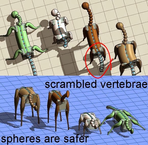
The problem with my vertebra component, it shows up the orientation quircks of repeaters. Not always easy to get the behaviour you were hoping for. If you look cerefully you will see that the cow's tail is a bit add. The individual components don't line up nicely, they just hang there like a string of tin cans behind a wedding car. So for the neck and head I chose the more forgiving geometry of a sphere. Just for now anyway.

For what it's worth, this all took place between 4.30am and 10.30pm on friday 2 August. (our weekend is friday/saturday and I'm quite certain that there were a couple of lengthy mid-day snoozes in-between Revit sessions :-)
I want to make animals. Or perhaps to model life in general. Organic Form, Evolution, Symbiosis, Embryonics. Those kind of ideas seem to chime with the very essence of BIM, Parametric Modelling, Form Finding ... all that stuff we have fallen in love with. I call it drawing, digital visual thinking, the grand tradition to which we all belong (assuming that there is an artist inside every one of us)

The first pic is something I did almost 3 years ago. Still haven't got around to posting this properly. It was inspired by a book I read called "Endless Forms Most Beautiful" by Sean Carroll. It deals with the role of Hox Genes in the development of Embryos and the surprising fact that may of the genetic switches that control the development of human embryos are recognisably the same as those that control fly embryos. There are some very nice diagrams which explain the modularity of various body plans. For example in vertebrates you always get a head, then a variable number of neck vertebrae, then a limb, then a variable number of trunk vertebrae, then another limb, then a variable number of tail vertebrae.

The parallel between DNA switches and Family Editor parameters struck me as interesting, hence my attempt at a modular family which builds simplified abstractions of bodies. Here is a closer look at my goose family. It uses arrays (number of vertebrae), visibility switches (to turn on the triangular section of the bird limb for example so that the wings look different from the back leg) Simple scale factors (to make the legs smaller than the wings) I'll take an even closer look if I get time.

I have a family called "05_Generic Starter" just 2 clicks away via my Tray Menu. It's just a box with 5 predefined parameters. I use it most of the time as a substitute for the Metric Generic Model template. Saves me a couple of minutes. I decided to make an adaptive version of this called "00_GMA-starter" The digits in the names are based on the old SFB system which we still use at GAJ. I suspect many British based practices still find this numbering system useful. Incidentally, the faded image behind the large text is created with a masking region, element over-ride set to 25% surface transparency. A neat little Revit DTP trick.

So straightaway the pumpkins adventure pulled me into new territory. I lofted my box from a Ref-Line rectangle. Actually I used a 4-sided polygon, a trick I picked up from Mr Revit Cat (Tim Waldock) Fastest way to create a rectangle centred on a point (the origin). I placed an adaptive point at the origin for good measure, nut I don't think this is necessary. I have a "BOX RIG". This first one dates from the beginning of August and I have used it repeatedly since then.

I want to make animals. Last year I did fruit and veg, so it seems a logical extension. Build on the previous 2010 attempt but make them more 3 dimensional and "organic". My first thought was to string together a set of box rigs and hang geometry within them. Transformations will consist of manipulating the relative proportions of these boxes.

by the way I'm doing all my paste-up in Revit here. Snapshots taken as I work (using windows wonderful snipping tool) drop these onto a sheet, add text, resize as needed, fake the odd drop shadow with a detail line ... Snip the end product straight off the screen to create the final jpeg. Works for all the nuts & bolts stuff. Fancy renders get processed in Sketchbook Designer.
Wouldn't it be rather nice if the Factory gave more weight to the Desktop Publishing side of Revit ? That's what the sheets capability is, right, dumbed down DTP ? I wish we were getting a couple of enhancements to this capability with each release. Image cropping perhaps, or brightness/contrast control, maybe even drop shadows eventually. It would be really nice to do concept design booklets directly from Revit. I digress.

Now I could have made boxes from ref lines, but why go to the trouble ? I made a conscious decision to start simple and see where it led. The Box Rig. Untick visibility for the boxes, or set them to show only at coarse detail level. Your choice. My next lightbulb moment was placing a point on one of the vertical edges of the box. It has NCP properties ! My first time to notice this. No need for an eleborate rig of ref lines. A simple cuboid will do. (Normalised Curve Parameter)

So I can hang splines within each box and loft body parts along the splines. And the boxes themselves can be set up to reshape parametrically.

Long tail, short tail, spindly legs, giraffe neck ... A picture explains it better.

Let's try to make a leg. Nothing too fancy, just a proof of concept. See the ladder rungs concept coming into play again. This was a fundamental feature of the Scalable Rectangular Rig that I stumbled on during last year's Pumpkin journey.

If legs are to become wings, or belong to lizards, they must be able to splay out sideways. Maybe the ladder can help here. Hang a ladder inside a box and drape your leg over that.

Take a quick look at the possibilities. If you make the box very narro and play with the leg section you can get a very straight and portly peg leg, suitable for a pig perhaps.

So what about a tail ? Tails are extended backbones so I threaded one spline between two boxes. Then I hosted 2 separate splines, 3d picked onto this first one. Use these to create repeaters. Make a new profile using the point-based method from my first 2 pumpkin rides. This has 2 spline-thru-points, symmetrical. I call this a mass profile but actually it uses the generic model adaptive template. It's a set of model lines, closed loop in a flat plane. Use it for lofting. In this case I just converted it directly into a component.

The problem with my vertebra component, it shows up the orientation quircks of repeaters. Not always easy to get the behaviour you were hoping for. If you look cerefully you will see that the cow's tail is a bit add. The individual components don't line up nicely, they just hang there like a string of tin cans behind a wedding car. So for the neck and head I chose the more forgiving geometry of a sphere. Just for now anyway.
For what it's worth, this all took place between 4.30am and 10.30pm on friday 2 August. (our weekend is friday/saturday and I'm quite certain that there were a couple of lengthy mid-day snoozes in-between Revit sessions :-)
No comments:
Post a Comment
I've been getting a lot of spam so had to tighten up comments permissions. Sorry for any inconvenience. I do like to hear from real people