Tuesday, May 28, 2019

SCROLL UP


This is a post that was overtaken by events in Paris, and my detour into the Gothic. It’s intended as the first in a series dealing with classical elements based on spiral geometry.


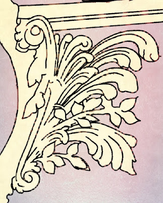
My first image is a hand sketch to illustrate the challenge of representing some of the more elaborate decorative detail found on some classical buildings. My recent work on the Corinthian capital begins to address this.


Related to the Corinthian is the Composite order. The two blur into each other at times, but essentially, if you treat the volutes as scrolls from an Ionic capital, you are getting into composite territory.


Very often there is a portion of egg and dart moulding between the scrolls, and quite possibly only one row of Acanthus leaves, so that the scrolls remain prominent.


You could argue that the volutes in Corinthian capitals are abstracted from plant forms, whereas Ionic scrolls reference the animal kingdom. Goat horns are symbols of Aries, my own birth sign, for what it’s worth. Other examples include snail shells, and the curled-up posture that centipedes and armadillos assume under threat.


The brackets that often “support“ pediments over doors and windows are called consoles. This term has taken on new meanings in the digital age, perhaps via the intermediary of the “console desk” basically a table top supported by scrolls.


Soane favoured elongated versions with elliptical motifs replacing the inner part of the spiral. I chose to create a more conventional version, because I want to develop methods for spiral motifs that can be repeated in different situations.


I started with some analytical sketches that explored possible modelling approaches. These were useful mental exercises, but in practice I took a different direction.


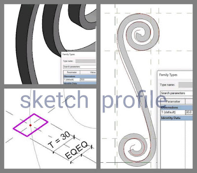
the next step was to trace a spline. Again I began rather ambitiously and scaled back to something simpler. Nothing in this post is rocket science. Sometimes common sense and adaptability are more useful than virtuosity.


The virtue of a spline in Revit is in its ability to scale proportionally, simply by stretching the end points. The long term goal is to be able to create new versions of the console relatively easily. They don’t have to be  completely automated and parametric. I’m happy to open them up in family editor and do a bit of pushing and pulling. Just as long as I don’t have to start again from scratch every time.


The spline becomes a sweep, thin at first, then gradually thickened and simplified. Two copies of the sweep define the shape and the width of a console bracket.


This is embellished with a couple of extrusions and pick-edge sweeps to shape the connecting surfaces. A loaded profile allows for rapid development of different versions


And so we gradually home in on the design I originally selected. That’s about as far as I got. I’m sure that future demands will lead to multiple variants on this theme, but not perhaps on Project Notre Dame which seems destined to consume my “spare time”for the foreseeable future.


So to conclude this post, an atmospheric image courtesy of Enscape3d and PIXLR. If only there were more hours in the day.


Tuesday, May 14, 2019

WEST END LADY


An interesting weekend. I chose to confine myself mostly to the West End, so as to make room for other collaborators. What can you say about the Facade? The sheer scale, the balance of horizontal and vertical rhythms, the clarity of form despite the profusion of sculptural detail. 


I began by tackling the arches at the base of the Bell Towers. In contrast to the solidity of the stout round columns that march down the nave, these piers present themselves as sinuous clusters of parallel ribs.


Without a point cloud or a definitive set of survey drawings it’s sometimes difficult to know where to start and conflicts often arise. You just have to throw yourself into it, and make some bold decisions. This often means modelling “in-place” at first and gradually working out how to break it down into modular components.


As the day proceeded, Europe came online, and then USA. I saved my work, and we upgraded the model to Revit 2020, which went smoothly enough. The organ loft acts as a bridge between upper rooms in both towers. These are a couple of metres higher than the Triforium galleries, so you descend about it dozen steps to access these.


After making a quick placeholder for the wood and metal of the organ itself, I reached instinctively for Enscape3d, but it wasn’t there. I guess I need to upgrade now that I’m using 2020.


 Unsure whether my complementary license would stretch to that I reverted to the slower process of Revit’s own rendering engine plus a bit of jiggery-pokery with Photoshop. 


Well into Saturday by now, and time to move outside. Cornices to be added, and heights to be adjusted. We have an elevation that looks quite convincing, so I’m trusting that, pasted behind a semi-transparent working view. 


There are two rhythmic horizontal bands that tie the Facade together and divide it into three sections. The upper one is quite open and delicate. I realised for the first time that the central portion of this forms a double decker bridge between the Bell Towers.


The lower band is a continuous array of statues, twice life size, each standing in its own niche. I had previously created a very crude substitute for the upper band. Now I needed to rough out the “standing men” in their sentry boxes.   


I’m quite proud of my “lego person” : two extrusions, supporting a sweep, topped by a revolve.  Choosing appropriate Revit native geometry to represent complex sculptural objects in a simplified abstract way ranks as one of my favourite challenges.  How can you fool the brain to engage its automated object-recognition response?  If you can manage that, people will see far more than is actually there.


Sunday afternoon is always a tricky time. You can feel the modelling coming to an end, pressure building to prepare a blog post. I didn’t devote as much time as I should have to cleaning up the file and establishing naming standards.  But perhaps I can squeeze in one more item.


Don’t know how many intermediate floors there are in the towers. I made a guess, added an in-place extrusion to define the spiral stair void, placed some doors for access. All this based on a few lines on the ground floor plan.


So that’s it for another weekend. The Slack group is getting quite lively and people are starting to take on tasks. Personalities interacting across the continents. Next weekend I really must put some order into the naming conventions … if I can tear myself away from the excitement of the modelling challenges for long enough :)


Monday evening and trying to finish this post. Daniel Hurtubise exported an executables version of the model using Enscape3d and shared it with us. That’s the source of these last few images.   Walking (and flying) around this interactive model is a wonderful way to reflect on the shortcomings of the current model and prioritise tasks.  It's also a great way to deepen my appreciation of the architecture.  The model is in white mode, which focuses attention on the forms rather than the materials.  Lady in White?


Tuesday, May 7, 2019

NOTHING LIKE A DAME


I begin this weekend, intending to treat it as a concept design submission. The goal is to have half a dozen sheets of drawings (plans, elevations, sections) several perspective views and a tidied up model with a fairly consistent level of development across the whole building. Let’s see what happens.


Thursday evening found me sketching ideas for vault family strategies on my phone. I knew that the curved ambulatories around the East end would be tricky but I was optimistic.


Friday morning revealed serious issues with the existing setting out. This would have to be resolved before embarking on the vaults. First thing to do is look more carefully. Peel off another layer of the onion. There are radial alignments where the flying buttresses sit. These were not working.

Also there should be curved sections of wall between the arches of the outer row, not free standing columns like the two inner rings. I decided to use a new background image. Maybe this plan was more accurate. Certainly easier to read.


The next detour along my weekend journey was distracting but positive. Conversations with potential collaborators, which I managed to get moved to Slack eventually. Four way conversations in full swing by Saturday.


I realised that there was a double grid at the transition from straight to curved, an offset of about 1.5m This was crucial in getting the radial alignments to work.

Along the sides of the nave I have columns nested into the arch families. This works well, but around the curve the columns need to be independent in order to fine tune their position and alignment.


All this took time. The second pass through the model can be frustrating. Work proceeds more slowly than during the first roughing out. But the complexity of the apse Geometry is quite fascinating. I would love to compare with other cathedrals. I wonder if someone has done this already.


Here there are 5 bays in the inner ring, 10 in the middle ring, and 13 in the outer. The first two rings are evenly spaced. But the third has grouped arches. This allows for the thickness of the hefty walls that anchor the flying buttresses.


So on the outer edge you have vaults that link 3 arches on one side to two on the other. Creating a sort of zigzag pattern. This seemed like a suitable challenge for Saturday.


 I tried the swept blend approach that had worked well for the radial vaults high above the altar. Actually, these need to be reworked now because the offset has disturbed their regularity. The Leica TruView site was really helpful in visualising the context here.  It really captures the spirit of Gothic architecture: bundles of circular ribs curving upwards.  The tricky part of the Swept Blend in this situation is the way the void extrusion cuts at an oblique angle to the second profile. 


Couldn’t get the swept blend to work for the zigzag. Too much irregularity. Can’t get the ends of the vaults to match the arches. So I opted for Point World, and lofted surfaces. Took a long time and the fit is still far from perfect. But I learnt a lot about the subtlety of these spaces.  This is all manually created with an in-place mass.  You could thicken the surface up using wall/roof by surface, but I don’t think the junction at the ridges will work out too well.  The alternative would be to use a closed profile for the loft, instead of a line.


Looking from above you get a feel for the nature of the challenge.  There are five wedge shaped portions of vaulting between the zigzag of the ribs.  The middle one is symmetrical, but the others are skewed.  It’s just the way things work when you divide the space up like that.  You can see the small gaps down the sides where the vaults meet the ribs. 


Of course, it’s always possible to generate a softer image that disguises the minor imperfections that leave me dissatisfied with my efforts so far.  “Fake News” you may say, but I think it’s always useful to step back from time to time and view your work from a metaphorical distance.  Between the groups of 3 arches there is a wider section of wall.  The round column is pushed a little further forward and there is a flat splay leading back to the arch.  There should be a horizontal line where the vault meets this splay.  Not happening.  Something wrong with the geometry but I’m not sure how to fix it.


There are 3 types of zigzag vault. I’ve done one instance of the pink type. One out of three. There are two different types that connect two arches to one (green and blue) Looks like I’m going to pass all these on to Alfredo now. Big sigh of relief. 


Alfredo very generously offered to host the model on his BIM360 site.  Ideally I would have liked Autodesk to host the model, but those discussions have not yet come to a conclusion and there are several people keen to contribute, so we went ahead.  There will need to be discussions about how we coordinate our efforts.  From previous experience with Project Soane, a naming system for the various elements will be helpful, so that will probably be my initial focus next weekend.


After uploading the model on Sunday afternoon, I had time for a bit more modelling.  Some adjustments to the main vaults over the choir and the apse.  Not complete, but enough to establish how the double grid is accommodated.  Then I roughly sketched in the intermediate flying buttresses around the apse.  This is another example of a “3 bays into 2” situation.  So you get two buttresses converging to meet at their highest point.  I have made them straight in plan at present, but actually they need to do a bit of a “dog-leg”


So we have a lot of fascinating challenges, and a small team of experienced Reviteers.  Let’s see what happens over the next few weeks.

There's nothing like a good collaboration.


Wednesday, May 1, 2019

WHOSE LADY ANYWAY?


I’ve been to Paris once in my life, and that was 40 years ago. Notre Dame doesn’t have any special symbolic meaning to me, but it’s an interesting example of French Gothic and an opportunity for me to explore a different period of architectural history after so long on Project Soane. But of course “my spirit is moved.”  This is a breathtaking space, even in crudely modelled, virtual form.  So I guess she is my lady from one point of view, and yours from a slightly different point of view.  The more we engage with her, the more she becomes "our lady."  Maybe that's an argument for a collaborative modelling effort.


My second weekend on this adventure began with a rethink of the Gothic cross vault that I made at the end of the previous session. I had failed to figure out the formulas needed to make it fully parametric, and resorted to manual adjustments to get the same rise over two different spans (W & B). Coming back fresh, it turned out to be fairly trivial. First set the rise you want (H), then calculate the two radii using basic Pythagoras. (RW & RB)


The vault itself is just a rectangular extrusion cut by two voids. During the week I had come across the Leica site (laser scan data) which has been made public. You can access 360 panoramas from each of the scan locations. This made me realise that there were flat roofs over most of the aisles around the East end.  Photos of a very nice wooden model also helped me to understand this area.


I came to realise that the triforium Gallery turns the corner where it meets the crossing. This allows a connection to the spiral stairs that rise from the ends of the transepts. Some of the impressively detailed models you see on the Web have missed this subtlety.  There are some benefits to using a BIM authoring tool.  It forces you to think in holistic terms about a real building made from buildable elements.

I also realised that the flying buttresses around the East end have a different shape from those along the nave. The angle is somewhat steeper, for example.


I had been wondering why the bays next to the crossing had a different glazing pattern, with a round window sitting below a shorter version of the usual pointed one … like an exclamation mark ! Suddenly it came to me. This serves to disguise the extra width required to accommodate the spiral stairs. When you have a row of identical bays, but one is wider, your brain picks this up in a flash.  But if that bay is different in some more obvious way, the difference in width tends to be overlooked.

To help blend this new pattern into the overall composition it is continued around the corner along the transept elevations.


The sexapartite vaults of the nave were always going to be a challenge. After a couple of abortive attempts, I came up with a dual strategy. The main portion is a formed by two instances of a nested component (a solid cut by a void). The four smaller side branches are surfaces, made in the Conceptual Massing Environment (Point World) and exported to SAT format. This is inserted into the parent family and mirrored to create the 4 instances needed. The various ribs are created as sweeps, using “pick edge” mostly. 


I need to rebuild the surfaces for the side vaults really but they look OK from a distance so let’s crack on. I’m leaving the difficult geometry of the vaults that curve around the apse for another weekend also.


Checking against the internal elevations given by Bannister Fletcher, I made some adjustments in heights and levels of the families I placed last week. Took the opportunity to add a little extra detail also, including the vertical ribs running down from the vaults to the round columns at ground level. 


With the main vaults in place I was able to fire up Enscape3d, place a few people for scale and generate an impressive view of the soaring internal space.  It’s interesting to compare this atmospheric perspective with a Revit 3d view, using a section box and flipping the building on it’s back like a stranded turtle.  Still quite a few vault missing, but I find it very helpful to have these two representations of the same space, generated from a common model, and viewable together.


Time to add some tracery to the glazing then. I wanted to try making this parametric. This will come in handy if I decide to tackle a few more Gothic buildings. 


One approach to controlling this level of complexity is to have a series of parameters all related back to width and height by formulas. I often prefer to use a series of reference planes and equality constraints.


I set up two different tracery patterns like this. They will repay further refinement when I have time, but first I wanted to go for some more test renders using Enscape3d


The space looked too empty so I added some chairs and people, plus the floor tiling material. This resulted in the images at the beginning of this post, and the panorama at the link below.  By now, the West Front was looking underdeveloped in comparison to the rest of the model, so I invested a bit of time upgrading families: splayed reveals to the entrance doors, arched recesses embracing the pairs of windows on either side of the central rose.  All these are still simplified placeholders of course.  I always enjoy the challenge of finding the right balance across the whole model.


Seems like half the world wants to jump on this project in some way. Realistically speaking, my model is not going to be used for the remedial work. (not sure why the press likes to call it "reconstruction".  Our Lady is still largely intact, as far as I know.)   The rose windows are a good example.  The geometry is much more complex than I have shown at present, but it's a good step forward from an empty circle.  Possible the only thing I like about the LOD concept is the idea that models develop by a series of evolutionary steps, gradually adding complexity as our understanding grows.


It’s a learning exercise for me, and potentially for others who may wish to join in. In a sense, Notre Dame belongs to the whole world and for many of us, the best way to express our concern is by making something.

If there are schools of architecture or building that would like to use this as a learning opportunity I am happy to share my model or perhaps to set up some kind of collaboration. 
Anyway, I felt the need to add some very schematic urban context for the exterior shots, now that it's looking more like a real building.  Some people for scale again.


Maybe it’s a bit like world Cup fever, when kids all around get out into the streets and create their own “mini-tournaments.”  I was watching videos of George Lakoff while working this weekend: embodied cognition, thinking with our bodies.  Humans have amazing cognitive abilities, but it’s all built off the “learning by doing” machinery we inherit from distant ancestors.  Drawing and making are incredibly powerful ways of understanding the world.  


Turning to the apse (I’m not really turning.  That’s an example of a metaphor, based on embodied cognition.  We apply the experience of moving our bodies in the real world to the “journeys” we take in our mental worlds)  But “turning to the apse” I decided to try making curved and tapered vaults without resorting to Point World.  This took a fair amount of trial and error, using a swept blend that “shoots past” its target (more metaphors) and is cut back by a void. 

I may go back to the sexapartite vault and try this approach there.  Interesting comparison.


Time was running out.  Quickly back to the West End.  I forgot to tell you about the doors.  I made them as pairs, not sure why.  Above the central entrance there is an organ loft.  I’ve made this too deep at present, but my parametric family couldn’t handle the shallower depth for some reason.  Anyway it was good enough to justify another “screenshot to file” from Enscape.  I’ve added a bit of dapple and pencil shading using PIXLR, just to soften the image.  The placement of the people turned out quite well, I think, helping to emphasise the drama of the space.


I generated a panorama also, so take a look at that.  Probably one more weekend to bring everything up to a similar level of development.  Then we shall have to see.  Back to classicism?  Allow Notre Dame to dominate my life for the next 3 years?  Bit of both?  Make similar models of several other Gothic Cathedrals for a comparative study? 

Who knows?