I have to admit that my first reaction to Marcello's scaling methods was to raise objections. "How practical are they really?" "Aren't you overstating your case a bit" "Yes, very clever ... but ..." Seemed a bit mean spirited though, so I had a go at the "Tuscan Column by Spline" challenge. (see this post) Not a big success ... but it jolted me into a much better understanding of basic Revit splines. What once seemed a somewhat clumsy tool has become a little gem. Actually this applies to many features of Revit's standard drawing toolkit. Full of hidden gems.

But back to Marcello's scaling tricks. I'm beginning to think he's a bit like Autodesk: very prolific, good at marketing, always up to something new ... :-) So what should we do when the tools we get from Autodesk disappoint ? Complain ? Whinge ? Write insulting remarks on an internet forum ? Marcello himself would say something like "thanks for the gift, now I'm going to bend it to my will" In other words, he's thrown out some interesting ideas. Some of them will fly, some of them may bomb. Doesn't matter. Grab a hold of one and see where you can run with it.

So following on from my curtain wall screens, I started to think about linear repeating details. You know the kind of thing. Egg and dart mouldings, classical balustrades, dentils, faience string courses, cast-iron facade panels. Lots of applications.
These things take a little while to model, and invariably you change your mind about the scaling of the design somewhere along the line. Also you might want to re-use that detail elsewhere, but in a different context. The edge detail for a table is scaled differently from the eaves of a Greek temple, but they could both contain egg & dart.

No I am NOT a big fan of fake classical, or whimsical period charm. Some of our clients insist on lots of decorative detail, usually islamic, but I grew up with the modernist tradition really. However, I am deeply interested in our built past, and I love to use Revit as a research tool for better understanding buildings of architectural note around the world. That would be my main motivation for developing better ways of modelling this stuff.
So I set out to use the line-based Generic Model template and embed a double-nested planting family in it, similar to the curtain wall technique. This turns out to be fairly easy. You need to get your head around the fact that scaling of planting objects is based on height, whereas a line based repeating module will rely on a Length parameter to control spacing.

I dealt with this by having a factor which captures the ratio between "Module" and "Height". Once again there is a lot of linking of parameters right down the nesting chain to the original planting family where the geometry is modelled. It's a bit of a brain-teaser first time around, but once you have it working then you can repurpose the family as many times as you like with relatively little effort.

My first attempt was a balustrade. Previously I have made these with the railings tool, which is fine, but rescaling is a bit of a mission. You need to open up a baluster family and edit each of the revolves and extrusions, one by one. Then adjust the spacings in the railing family, separately for horizontal and vertical. This all gives you much finer control than simply scaling the whole thing up, but it's not the fast, responsive tool that you might want during early design explorations.
My line based family is very easy to use. Two parameters control spacing and height, all the rest is automatic. You might say that balustrades don't vary much in height, so why all the effort to make them scale automatically ? Well actually this kind of classical detail is used in various contexts. It might be a capping detail to a low wall (400mm high ?) , or it could be a small detail on top of a wooden screen (150mm high ?) or it could be the roof line to a prominent public building (2m high ?) I think scalable is useful. Getting the top rail to scale up is easy enough. Take advantage of the inbuilt scaling of splines. All good.

In a new situation I can use one I made before and scale it up or down to suit. Later on I might revisit the geometry of the embedded component, but at least this technique gets me up and running in a jiffy. Quick, responsive early design with smooth continuity of workflow as we progress to detailed design and fabrication. Once again, after you've set one of these up the rest are straightforward. So I had to do an egg & dart. The modelling itself is a little bit tricky: solids & voids, swept blends, a revolve, couple of extrusions. Not bad for a first try. Scales a treat.

You just have to drill down to the original planting family. Replace the 3d geometry. Load back, load back, load back. Give the line-based family a new name, you already have types with different sizes. Just adjust & rename these to suit the new geometry. Second attempt is a running freize, Greek style interlocking key pattern. Piece of cake.

At this point I started to wonder about "Sectioning". Planting families don't section (likewise Furniture, Plumbing Fixtures etc) Generic Models do. So what happens with the double-nested planting geometry inside a Generic Model. Works fine.
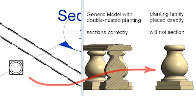
So what about VG ? Hide the planting category. The planting geometry nested inside a Generic Model is still visible. Great. Applying a material to the planting category in Object styles does affect the nested geometry but that is easily over-ridden with a material parameter. All in all these line-based families have enormous potential. Much more so than the Curtain Wall method IMHO. Curtain Walls with double nested panels have to be an exact multiple of the module in both directions. You need to disallow wall joins, otherwise you can get some unintended strange effects, overlapping panels, rows of little baby panels along the top, Still potentially useful, but not as robust as these line-based items.

I set about attaching my egg & dart planting object to an inclined ref plane (within the planting host) and adding a running moulding ( a sweep within the line-based family) Required a few equalised ref planes to get the sweep profile to scale up proportionately.

I added a bead & reel running ornament below the egg & dart, not universal, but very common. Just a series of revolves. It's worth thinking about all the parameter linking you would need to make an assembly like this scale up with the module of a line-based family if we didn't use the double-nested planting technique. I'm sure it could be done, but not without some sweat and tears.

Here it is, all rigged up and ready to go. This is a front elevation of the line-based family.

I think it's time to do a bit of rendering, and of course to put the scaling through its paces properly.

There are many versions of the egg & dart. It's easy to imagine that Classical Architecture works to a formula, just because there are many recognisable themes and it all seems to "belong together". But as I have remarked before, if you look closely, you soon realised just how much room for interpretation there is. If you want to stay within the spirit of the Renaissance, then "cut & paste" should have no place in your thinking. So after browsing through my collection of photo references I set about another version of egg and dart. This time I stayed more faithful to real-world methodology. To make an egg & dart moulding in wood, you start by running an ovolo (quarter round) So I took a quarter-round sweep (actually quarter ellipse) and cut the edges off with a void extrusion.

Next came a half-elipse void to cut out the hollow where the egg will sit. The egg is also a part-elipse revolve. And the dart is made by taking a second sweep, similar to the first but smaller. Once again use a cookie-cutter void to trim away the edges.

The result is a repeating element which has a more horizontal proportion than my first version. The dart is more elaborate, with an arrowhead below a circle.

Load this up, make a few types, use the material parameters and we're ready for another render.

Weekend wasn't quite over, so I thought I would try a row of dentils. Now these can be just simple rectangular solids. No need for the DNP trick in that case. Probably better to use X,Y,Z parameters and retain the ability to vary the proportions. But quite often there is some elaboration of the shape. I chose one from the Opera House in Graz. ( I was there last christmas visiting my Grandson) This time the sweep is a separate element, a wall sweep in fact. One of the drawbacks of the line-based families is that they don't mitre at the corners. Wall sweeps handle mitres with ease.

So there is my basic dentil. Double-Nest it and put it in a line-based family. You can vary the size and the spacing independently using the scaling factor that previously allowed me to accomodate differently proportioned egg & dart modules. And one final render to take us home. I'm not quite happy with the window-head detail. It would probably look better with a little bracked at either end framing the dentils, but I ran out of time. At least it illustrates the ease with which these families can be re-sized. And once again I found that my ability to manipulate splines is becoming more fluent every time I set up a new moulding profile. Using scale, stretch, rotate and nudge to vary the proportions of the different segments in a complex moulding. The hidden joys in Revit's 2d drafting tools never cease to amaze me.


But back to Marcello's scaling tricks. I'm beginning to think he's a bit like Autodesk: very prolific, good at marketing, always up to something new ... :-) So what should we do when the tools we get from Autodesk disappoint ? Complain ? Whinge ? Write insulting remarks on an internet forum ? Marcello himself would say something like "thanks for the gift, now I'm going to bend it to my will" In other words, he's thrown out some interesting ideas. Some of them will fly, some of them may bomb. Doesn't matter. Grab a hold of one and see where you can run with it.

So following on from my curtain wall screens, I started to think about linear repeating details. You know the kind of thing. Egg and dart mouldings, classical balustrades, dentils, faience string courses, cast-iron facade panels. Lots of applications.
These things take a little while to model, and invariably you change your mind about the scaling of the design somewhere along the line. Also you might want to re-use that detail elsewhere, but in a different context. The edge detail for a table is scaled differently from the eaves of a Greek temple, but they could both contain egg & dart.

No I am NOT a big fan of fake classical, or whimsical period charm. Some of our clients insist on lots of decorative detail, usually islamic, but I grew up with the modernist tradition really. However, I am deeply interested in our built past, and I love to use Revit as a research tool for better understanding buildings of architectural note around the world. That would be my main motivation for developing better ways of modelling this stuff.
So I set out to use the line-based Generic Model template and embed a double-nested planting family in it, similar to the curtain wall technique. This turns out to be fairly easy. You need to get your head around the fact that scaling of planting objects is based on height, whereas a line based repeating module will rely on a Length parameter to control spacing.

I dealt with this by having a factor which captures the ratio between "Module" and "Height". Once again there is a lot of linking of parameters right down the nesting chain to the original planting family where the geometry is modelled. It's a bit of a brain-teaser first time around, but once you have it working then you can repurpose the family as many times as you like with relatively little effort.

My first attempt was a balustrade. Previously I have made these with the railings tool, which is fine, but rescaling is a bit of a mission. You need to open up a baluster family and edit each of the revolves and extrusions, one by one. Then adjust the spacings in the railing family, separately for horizontal and vertical. This all gives you much finer control than simply scaling the whole thing up, but it's not the fast, responsive tool that you might want during early design explorations.
My line based family is very easy to use. Two parameters control spacing and height, all the rest is automatic. You might say that balustrades don't vary much in height, so why all the effort to make them scale automatically ? Well actually this kind of classical detail is used in various contexts. It might be a capping detail to a low wall (400mm high ?) , or it could be a small detail on top of a wooden screen (150mm high ?) or it could be the roof line to a prominent public building (2m high ?) I think scalable is useful. Getting the top rail to scale up is easy enough. Take advantage of the inbuilt scaling of splines. All good.

In a new situation I can use one I made before and scale it up or down to suit. Later on I might revisit the geometry of the embedded component, but at least this technique gets me up and running in a jiffy. Quick, responsive early design with smooth continuity of workflow as we progress to detailed design and fabrication. Once again, after you've set one of these up the rest are straightforward. So I had to do an egg & dart. The modelling itself is a little bit tricky: solids & voids, swept blends, a revolve, couple of extrusions. Not bad for a first try. Scales a treat.

You just have to drill down to the original planting family. Replace the 3d geometry. Load back, load back, load back. Give the line-based family a new name, you already have types with different sizes. Just adjust & rename these to suit the new geometry. Second attempt is a running freize, Greek style interlocking key pattern. Piece of cake.

At this point I started to wonder about "Sectioning". Planting families don't section (likewise Furniture, Plumbing Fixtures etc) Generic Models do. So what happens with the double-nested planting geometry inside a Generic Model. Works fine.
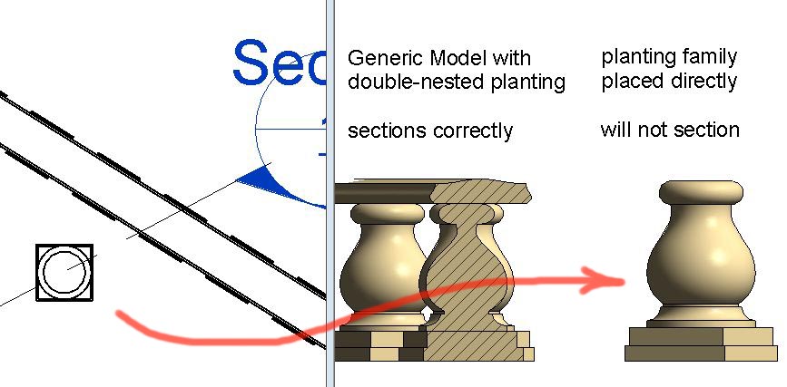
So what about VG ? Hide the planting category. The planting geometry nested inside a Generic Model is still visible. Great. Applying a material to the planting category in Object styles does affect the nested geometry but that is easily over-ridden with a material parameter. All in all these line-based families have enormous potential. Much more so than the Curtain Wall method IMHO. Curtain Walls with double nested panels have to be an exact multiple of the module in both directions. You need to disallow wall joins, otherwise you can get some unintended strange effects, overlapping panels, rows of little baby panels along the top, Still potentially useful, but not as robust as these line-based items.

I set about attaching my egg & dart planting object to an inclined ref plane (within the planting host) and adding a running moulding ( a sweep within the line-based family) Required a few equalised ref planes to get the sweep profile to scale up proportionately.

I added a bead & reel running ornament below the egg & dart, not universal, but very common. Just a series of revolves. It's worth thinking about all the parameter linking you would need to make an assembly like this scale up with the module of a line-based family if we didn't use the double-nested planting technique. I'm sure it could be done, but not without some sweat and tears.

Here it is, all rigged up and ready to go. This is a front elevation of the line-based family.

I think it's time to do a bit of rendering, and of course to put the scaling through its paces properly.

There are many versions of the egg & dart. It's easy to imagine that Classical Architecture works to a formula, just because there are many recognisable themes and it all seems to "belong together". But as I have remarked before, if you look closely, you soon realised just how much room for interpretation there is. If you want to stay within the spirit of the Renaissance, then "cut & paste" should have no place in your thinking. So after browsing through my collection of photo references I set about another version of egg and dart. This time I stayed more faithful to real-world methodology. To make an egg & dart moulding in wood, you start by running an ovolo (quarter round) So I took a quarter-round sweep (actually quarter ellipse) and cut the edges off with a void extrusion.

Next came a half-elipse void to cut out the hollow where the egg will sit. The egg is also a part-elipse revolve. And the dart is made by taking a second sweep, similar to the first but smaller. Once again use a cookie-cutter void to trim away the edges.

The result is a repeating element which has a more horizontal proportion than my first version. The dart is more elaborate, with an arrowhead below a circle.

Load this up, make a few types, use the material parameters and we're ready for another render.

Weekend wasn't quite over, so I thought I would try a row of dentils. Now these can be just simple rectangular solids. No need for the DNP trick in that case. Probably better to use X,Y,Z parameters and retain the ability to vary the proportions. But quite often there is some elaboration of the shape. I chose one from the Opera House in Graz. ( I was there last christmas visiting my Grandson) This time the sweep is a separate element, a wall sweep in fact. One of the drawbacks of the line-based families is that they don't mitre at the corners. Wall sweeps handle mitres with ease.

So there is my basic dentil. Double-Nest it and put it in a line-based family. You can vary the size and the spacing independently using the scaling factor that previously allowed me to accomodate differently proportioned egg & dart modules. And one final render to take us home. I'm not quite happy with the window-head detail. It would probably look better with a little bracked at either end framing the dentils, but I ran out of time. At least it illustrates the ease with which these families can be re-sized. And once again I found that my ability to manipulate splines is becoming more fluent every time I set up a new moulding profile. Using scale, stretch, rotate and nudge to vary the proportions of the different segments in a complex moulding. The hidden joys in Revit's 2d drafting tools never cease to amaze me.


