Sunday, January 31, 2016

NEW YEAR BROOM SWEEPINGS

For some time now I've been meaning to spruce up the blog a bit and some of you may have noticed that I had a go at the "Pages" ... those buttons up near the top.  I added a "Pumpkins" page and reorganised "The Way We Build" and "Downloads" a bit.  Hopefully this will make it easier to mine my ramblings for the good bits.

You can come across all kinds of interesting things while cleaning up after a long period of neglect.  I do intend to make more freebies available.  Mostly they are just waiting to get cleaned up a bit.  Anyway I received a request a couple of weeks ago to post the lightweight stylised car family that I described almost 5 years ago now.  Can't believe it's been that long.

DRIVE MY CAR

One caveat here.  The family contains detail items that I downloaded elsewhere, so I hope it doesn't cause offence for me to pass these on.  They were in the public domain, and I'm not making any money out of them, but they are not my work.


I did embed this car in a parking family at some stage, and we've used that combo quite a bit in real live projects.  You can choose to show the car (or not) on an instance basis, so it's a useful way of adding a bit of "realism" to your parking layout. You know, "let's sprinkle a few cars in there to liven the drawing up a bit."  You don't want to do that with some embedded 3d cad vehicle, but this lightweight item seems to be just fine.  Orthographic views only display 2d content.


It would be nice to develop a few more of these for variety, but that might take another 5 years :)  I did make a delivery vehicle version, but that's not got 2d elevations embedded at present.  So much "finishing off" that I could do ... how will I ever find the time ?  So for now I'll just throw in what I have.  Please feel free to improve these families and send them back to me.  I've been saying for a very long time that the Revit content out their is not as good as it could and should be.  A group of experienced end users, fully committed to open-source sharing could surely change that.  Don't you think ?


You can control the lineweight & colour of the 2d elevations from Object Styles/Imported Categories/Imports in Families of course. Or use the view specific version under VG.  I made them as entourage, but you could change the category if you want to.
So that's it for now.  Download the families here, and I hope you find them useful.

LINK

Sunday, January 24, 2016

LEFT-RIGHT, LEFT-RIGHT

I'm pretty sure Steve Stafford will have posted about this at some point, but I don't think it's anywhere near as well known and understood as it should be so here goes.

After more than a decade of using Revit, last week a penny finally dropped inside the rusty cog-wheels of my grey matter.  Have you ever been frustrated by dimension chains losing some of their references when you reload a door family, or swap types, or whatever? This has been bothering me for a while.  Sometimes it even happens when I duplicate a type within the same family. Sometimes dimensions jump to new positions, even rotating through 90 degrees perhaps.


I am in the process of making new standard door families for use at GAJ.  At a rough guess I would say it's my 4th or 5th attempt to tackle this crucial standardising task.  Over here, doors are usually defined by their structural opening sizes. That's the dimension you give to the contractor. It appears on the dimensioned floor plans, and in the door schedules.  The width of the door panel, and the resultant clear opening size are derived values, depending on the jamb detail and door leaf thickness.


Most door families are driven by the Width and Height parameters.  The Rough Width & Rough Height tend to be derived by way of formulas.  This has caused some confusion in our office.  So I set out to make Rough Width and Rough Height the labelled dimensions, demoting Width & Height to the status of calculated values.  I know some people like to make new shared parameters with more explicit names (Structural Opening Height, Door Panel Width etc)  But I prefer to use what's built in if I can.

In the process of re-labelling I had to think carefully about which reference planes I was using, and to test the stability of dimensioning that resulted.  It turns out that by far the most reliable approach is to use the hardwired "Right" and "Left" for the ref planes you intend to dimension (Rough Width in our case)  Even better, choose "Not a reference" for the other planes.  Then your minions are much less likely to pick the wrong plane by accident.  Any other family that's made in the same way, with the driving dimensions attached to "Right" and "Left" can be swapped out with confidence. 


It's obvious to me that this is intentional behaviour.  That's why families have these built-in "Special" reference planes.  Those are the ones that you are going to pick up for dimensioning in your document set, and they are going to be stable, because Revit recognises them when you swap out a family.  But talking to other experience people in our office, I couldn't find anyone who was aware of this.  Maybe it's in the documentation somewhere, but I don't think it's widely known.

This is a real shame because it's absolutely fundamental and anyone making loadable families that are going to be dimensioned in a construction drawing set should have a firm grasp of the implications.

You need to be clear in your mind what is the critical overall dimension for this type of object.  In our case it's the edges of the "Structural Opening".  Then you need to make sure that you use the "Right" and "Left" reference planes to define these edges in all your families.  And do think carefully about which parameters you want end users to input when defining the size of doors.  What is the standard industry practice where you are ?  Think like a contractor.  That's often the best advice when determining BIM standards and procedures. 


Thursday, January 14, 2016

PALLADIO FOR DUMMIES


I started this stuff 2 years ago and used it in my Urban Design session at RTC Chicago.  Should have made it to the blog long ago.  I have this file with a bunch of rather odd studies inside. 
They're odd because of the scale and the way they are arranged.  Not the usual sort of thing to do with Revit.  I'm putting Palladio's villas into highly abstracted context models.  It was a way of testing out various ideas I had on working with Revit at Urban Design scale.


When I started collecting reference material. perhaps 20 years ago, I was only aware of a handful of villas, but these days anyone can download a long list from Wikipedia and bring up a page full of images for each.  And of course they have collectively become a World Heritage Site.  Armed with the names, you can find them on a mapping service like Google or Bing and make a guess at what the surrounding landscape was like over 400 years ago.


As I've said before, BIM offers a splendid toolkit for doing this kind of research.  I'm not attempting a strict academic history here, more considered the reflections of an enthusiast.  It's fascinating to come back to work like this.  You put in many concentrated hours of effort, leave it behind, then return refreshed. 

Architects work for people with money.  That's one of the reasons I gave it up as a young man.  Palladio's villas were built to advertise the wealth of a Venetian upper stratum, some filthy rich, others aspiring local businessmen.  I liked Villa Badoer because of the clear East-West divide and the contrast between formal life in the Big House and the rough and tumble of the village.  The client could stand on his front porch and look down upon the dwellings of his farm hands, across the bridge.


All the buildings here are family objects.  Only the villa itself is specially made, the rest use the same general-purpose family common to all the studies.  How to quickly sketch out ideas on a grand scale using Revit ?  That was the question I was asking at the time.  The tree family that I developed along the way was shared some time ago  ( the-universal-lollipop-tree ) 

Again it's a single, flexible family that can be quickly scattered around and varied.  We don't want too much variation or detail which might detract from the bigger picture. 


The Veneto is a fertile plain, the north-east portion of the great Po valley.  Venice made vast sums of money by monopolising long distance trade for centuries.  They controlled the market in spices and silks coming into Europe from the East.  But in Palladio's day things were changing.  The Ottomans Turks were edging them out of the Eastern Med, and the Portuguese had reached the Indies by a different route.  The response was to turn back to Agriculture.  Venetian Nobles were investing their ill-gotten gains in country Estates, working farms that were expected to turn a profit, but also symbols of there continuing importance. 

The plain is riddled with waterways: rivers, streams and canals.  We met one at Villa Badoer and here's another.  Villa Pisani at Montagnana was built for a mill owner, opposite the main town gates.  It's one of the few old medieval towns to still have its walls intact.  Look it up.  Unlike most of the other villas, this one fronts straight on to the road.  It's almost urban, one foot in the town and one foot in the country.  The house is actually built over a stream.  It's fairly obvious that this has been diverted: canalised to make way for the town walls and used to supply water to the moat, I guess.


I'm doing the water as split regions in flat sheet of topography.  Maybe I will try out the Site Designer tools for that Moat at some point, but for the most part this Urban Design stuff is simpler if you can keep things on the level.  Doesn't always work of course.  Some site contexts make no sense unless you model the terrain.  But for most of these studies I kept it flat.

The roads are done as floors, so they just float over the rivers.  It lacks the 3 dimensionality of a proper bridge if you zoom in close, but we're focusing on broad brush issues.  It is possible to do roads as walls.  You set up a type of wall for each width of road and keep them very short indeed.  But these roads often vary in width in a very organic way, so I reverted to floors.  Takes a little bit longer, but I think it's worth the effort.


Now for the small villages, I used individual houses, but Montagnana is a different case.  It was going to be a lot of effort and also I felt that it was distracting attention from Villa Pisani itself.  So to represent the town as "Context", I've modelled it as an in-place family made up of just 3 extrusions.  The three different materials and the non-orthogonal shapes get across the idea of an organic layout while keeping things relatively simple and homogenous. I tried varying the height of the extrusions but it didn't see to add any value.


I added the stream in this weekend, having noticed that the Villa sits on top of it.  You can actually see this in Street View funnily enough.  There is an arch over the watercourse below ground level, clearly visible from the road.  Now one of my references mentions a "workshop" in the house.  Does this mean that he operated a flour mill from his own house?  There are blind recesses in the corner that sits over the arch instead of normal windows, so they are not habitable rooms.  Maybe he just had a small wheel for repairing tools, turning wooden parts for his mills etc. 

This is a nice example of the kind of close observation and questioning that results from using BIM tools for historical investigation.  I met it time and again in Project Soane and it's cropping up in these villa studies.


I had forgotten just how I set about making the villas themselves.  I knew they were generic families made up of standard components as far as possible, but I was a bit hazy on the finer points. I remembered putting some effort into Villa Piovene so I decided to revisit this.  It's in a separate file because this is one case where flat topo wasn't going to do the job.  I got someone to help me bring in topo from Google Earth via Sketchup and CAD (my Sketchup skills have atrophied from neglect.)  You can actually see the crude rectangular matrix that results.  It's good enough for present purposes though.


Opening up the Villa Family there are perhaps a dozen extrusions, a couple of sweeps, and three nested families: an all purpose roof, a classical column, and a "window". 


The roof family has instance parameters for Depth and Width, Angle and Fascia Depth, plus the ability to assign "Hip" properties to Left and Right separately.  This just slides a void across (via an IF formula)  The angle is derived with a simple trig formula.  You can use join geometry with 2 roof families to get a hard line at the valley.


The window is a simple face based family with two extrusions: one solid, one void.  I've been using paint to apply glass material within the master family.  Type parameters because there's a lot of repetition of standard of sizes.


The column is a real column that responds to Base Level & Top Level when placed in a project.  This makes it a bit weird within family editor, but you can just have both set to Ref. Level and type in a height.  I'm not going to attempt a step-by-step description.  I had completely forgotten how this worked but it's quite cute.  Some formulas to derive a module from the height (a reporting parameter called HR)  There is a variable slenderness ration in there and lots of equalisation to control reference planes to which geometry is locked.


The curved mouldings are sweeps which resize by locking to ref planes.  And the crude "dumbbell" which switches on to turn Tuscan into Ionic is a revolve that locks to the same ref planes.  I wanted a coarse-scale classical column for roughing out ideas in a broad-brush way, and it does the job.  I'm happy to share if there's a demand.


Palladio actually designed two villas in quick succession on this hillside.  Two competing families: Piovene and Godi.  In my book, the Piovenes won, largely because they had the better site and could stretch out along the contours, whereas the Godi villa is forced into sitting sideways.  Also, they don't seem to have had the money to finish off the exterior, it's very bland and missing features that Palladio included when he wrote it up in his "Quattro Libri".  Perhaps they spent too much on earthworks creating a level terrace and were more interested in saving the rest for internal frescoes. 


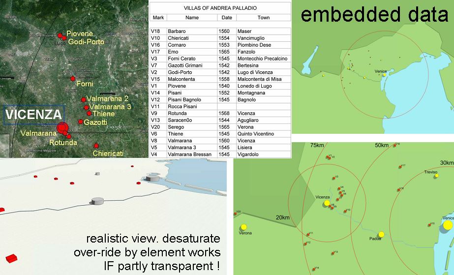
I think the image above illustrates the BIM approach as opposed to generic modelling.  There are a couple of perspectives: (showing the villa from the town, and the town from the villa) which could have come from Sketchup or whatever, but the 2 orthographic views and the page layout take us into the realm of BIM.  Next step would be to make more use of embedded date, I guess.


Well I made a start on this with an even weirder element within my main study file.  This is a map of the whole area.  It's made to scale because Revit doesn't do 100km.  Towns and villas are represented by oversized generic families.  All the villas use the same representative element, but there are shared instance parameters to represent things like Date and Town.  We could go on to add other comparisons, perhaps to classify the clients into types, size of villa maybe.  We could also group the designs by various criteria: linear or compact; Tuscan, ionic of Corinthian; does it have side wings (Barchese)


Villa Cornaro is an interesting one because it's basically just another house along the High Street, diagonally opposite the church and somewhat grander than its neighbours.  Piombino Dese is effectively a linear development along the highway from Vicenza to Venice. I don't have any old maps so all I could do was simplify and reduce the size of the town.  But I'm not trying to give an authoritative historical view here.  The main thrust was to develop a method for doing urban studies fairly quickly in Revit and to deepen my understanding of Palladio's' villas along the way.


Villa Saraceno gives us the opposite scenario: an isolated farmstead well outside town.  For many of his schemes he showed symmetrical side wings, often colonnaded and intended as functional farm buildings.  Quite often only one side was built, and often extended in an informal way at a later date.  I guess it makes more practical sense to group the messy, business end of things to one side rather than splitting it with the formal, entertaining area in the middle.  We're getting into the area of Classical Symmetry versus Gothic Improvisation.  More on that another time.

I made a start on a few more villa studies, (Barbaro, Emo, the Rotunda, Gazotti) but nothing that is worth showing yet, except for Villa Poiana.  I've always thought this is rather a strange one, not quite as stark as Villa Godi, but certainly lacking finer detail, and the scale is quite odd.  It looks much smaller than it really is for some reason.  So how big is it, actually?


One of the challenges with this kind of work is getting the size right.  I never know how much to trust the measurements you get from Google Earth and the numbers shown on Palladio's drawings are difficult to interpret.  Many sources claim that they represent "Proportions" but this doesn't make any sense to me.  Since when do numbers like 26 and 34 belong to the same system of proportions ?  Looking closely, there is a "P" before the number and I suspect he is using the Venetian foot (Piede) which is given as 348mm in Wikipedia.  That would explain why conversions based on an imperial foot give significantly smaller buildings than Google Earth or Bing would suggest.

I decided to do some 2d drafting (in Revit) before making any more villa families, and I started off by doing this on a drafting view in the same study file.  This was probably a mistake.  It's not easy to transfer drafting lines from project to family.  This makes the creation of detail items that are tailored to a particular project much harder than it ought to be. (grumble, grumble) 


For the floor plans, I used a filled region.  This is quite easy to transfer.  Just go into sketch mode, copy the sketch lines, go to your family, enter sketch mode, now you can paste the sketch. 
It would have been better to do this 2d drafting in a Detail Item family.  You can place images, scale them and trace, just like in a project, BUT ... you can place the result either in a project or in a family.  One other small annoyance, Graphic Display Options is not available in the view properties within Family Editor, you have to go down to the bottom and find it on the pop-up list, (above Wireframe).  Then you can set a transparency level so that the image is visible below the filled region (which I set to solid red so it stands out against a black and white plan)


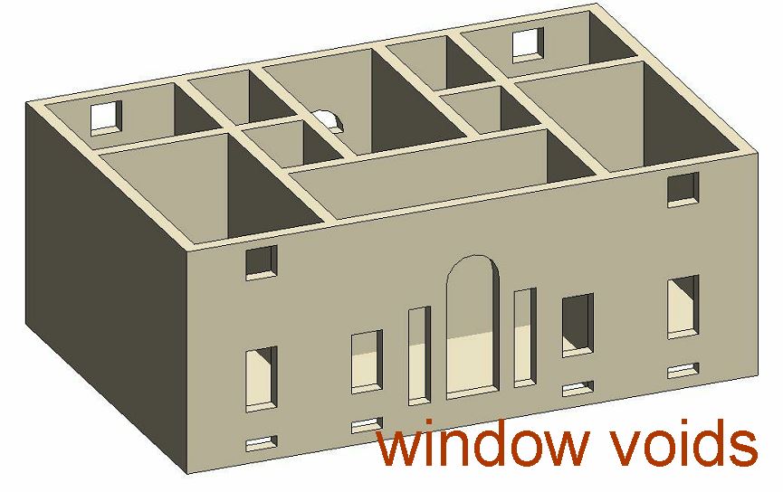
So back to Villa Poiana and I have an extrusion.  This time I am picking up the internal wall layout, (it's an experiment).  To transfer the detail lines from my drafted elevation I resorted to a CAD export.  Seemed to be the easiest way to transfer from project to family editor.  I ended up with a detail item that has both plan and elevation, so I added instance visibility switches.  I can't be bothered to make separate families.


Placing the detail item with the embedded CAD elevation over a "front" view, I can trace off voids for my openings.  Copy these to the back and adjust them (slight differences in elevation)


Then I'm adding some extrusions hosted on the face of my "walls", again traced off the detail item in elevation view.  Couple more extrusions in plan for the plinth and a sideways one for the stairs.  All this may seem a bit unholy.  Why am I using Revit in what amounts to a kind of "sketchup mode"?  Some of you will be getting quite upset I imagine.


Well, families are so much easier to handle than links in the kind of study I am doing here.  That's number one.  I've go a 750k family that I can flip around with the spacebar, and tag, and schedule ... need I go on?  Then secondly, I want to suggest that there is some merit in being able to demonstrate to "Designers" that you can do "freehand" modelling in Revit quite effectively.  Maybe it's another tactic for nudging them into the BIM fold, because we surely need more of them to make the move.  Common ground.  We need more of it.


Anyway I went on to model the roof.  Again it may seem strange to do this with extrusions instead of the system tool, (which of course is not available in Family Editor).  But actually it's not too hard.  Again, I'm not advocating this for working drawings of a building.  These are indicative families for use in Urban Design studies.  That's all.  They have a place.


And that's it.  I put Villa Poiana into my study and generated a couple of views.  I've developed some useful techniques and I've learnt a lot about Palladio's Villas, but there's an awful lot still to do.  Time ran out, work beckons.  See you next time.  

Oh one last thing ...

Why can't I right click and go "New Drafting View" just like I would do for a Schedule or a Sheet.  Instead I have to right click, scroll down to "Duplicate View", go to the fly-out, and choose "Duplicate", which will create a new drafting view with nothing on it. 


Monday, January 11, 2016

CLOUD 9 (1/2)

This is  a little bit of nonsense from the middle of last year.

Sometimes odd little things just crop up.  I'm sure I knew about this before but it had slipped way below the radar.  "Measure along an element" combined with Tab returns the length of a chain of elements.  And into the bargain you get this quite impressive display of temporary dimensions.  Not sure what I would do with it, but more data is better apparently so lap it up.


Then I read a post about copy-pasting revision cloud sketches into detail lines (I'm afraid I've forgotten the source).  I stumbled on this myself about a year ago, but didn't do much with it.  Just occasionally you want to cloud something that isn't actually a revision.  Maybe it's a problem with the linked structural file, maybe it's just "we showed this feature two issues back but you seem to be ignoring it".

I was a bit surprised by the statement that you can use the cloud in a filled region.  Doesn't work like that for me.  You can paste the lines in alright, but all you get is the underlying polygon, no curvy segments.


But that led me to thinking, "what about a detail item".  This was quite exciting, I thought I'd discovered a hidden gem.  The curves came in perfectly and I even managed to get parametric scaling working. 


Sadly though, despite the curves being fully intact in family editor, they don't transfer back to the project environment.  It's just a rectangle.


Still, my mind was racing away by now.  Isn't this really a lot like a line-based detail item ?  So I quickly knocked one of those up and it turned out to be surprisingly easy to get it working.  Put this back into my rectangular rig and reloaded.  It works, but something doesn't look right.


That's when I realised that in the actual revision cloud segments, the meeting point between the two arcs doesn't lie on the straight line.  No problem, this is also easy to set up.


Still, my little cloud was a bit too regular, so I threw in one of my false starts to mix it up a bit.  Also set up a parameter for varying the proportions of the underlying rectangle.


All very good, and the journey was fun, but when I stopped to reflect, I decided that just drawing directly in the project with the line-based family was going to be the most effective strategy.
008
But by now my mind was wandering all over the place.  What about a two-pick family that defines a rectangle ?  So I set up a rather elaborate rig with angles to define the proportions of said rectangle and tried locking lots of my little "2_arc_detail_items" in place.


Of course that was asking a bit too much.  Everything worked fine until I tried to change the angle, then it broke.  Probably locking families to families I thought (by mistake)  Easy to test, use the rig to drive a simple rectangular filled region.


That worked like a treat, so the principle is OK, but trying to lock 6 detail items each with 3 planes to be constrained was somewhat daunting.  How many retries would I have the patience for?  Wait a minute though.  Locking a rectangle is easy enough and I already made a rectangular cloud.  Just need to adapt that one.   Here's a bunch of "2 click" rectangle families (draw the diagonal)


This did the trick.  Changed the rectangle family from 4 segments to six.  Flexed it thoroughly.  Nested into the diagonal-rectangle rig.  Align and lock.  And it works.


None of this is particularly earth-shattering, but it was an interesting exercise in squeezing unusual behaviours out of family editor.  And along the way I came to realise what a neat idea the two-pick pair of unequal arcs was when someone on the original Revit team thought it up.  If only we could recapture the freshness of those early insights.  Wouldn't that be something ?


Sunday, January 3, 2016

PIE CHART IN THE SKY

I've been going through various Dynamo tutorials that have been sitting patiently on my hard drive waiting for me to finally "find the time"  I enjoyed building this simple graph that throws out a range of numbers, uses them to place points in a row and then wiggles one of those rows by feeding a sine wave into the Y axis.


One way to check if you absorbed an idea is to reapply it to a slightly different situation, so I turned the whole thing on its side and wiggled both rows to create a rippling surface.  This is all done with Dynamo running on top of a conceptual mass family: Point World, because I'm using points.


So when you switch off Dynamo, or save out the family to an RFA, you end up with a frozen wiggly surface, which you can use for "Roof by Face" and of course you can go back to Dynamo any time to thaw out your surface and use the sliders to quickly generate multiple variants.  In this case I have six active sliders, including different amplitude controls for left and right. 


I think I forgot to put in a width slider, but that could be added.  Maybe I should do a "node to code" while I'm at it and produce a black box with 7 input sliders and a single output.  But instead I got carried away with the resemblence to the little school house that Gaudi built in the corner of the Sagrada Familia building site.  This is not it, but rather a fantasy building inspired by the same idea.


Just before the weekend began I was talking to one of my good friends in the office, a young Egyptian architect with a passion for design, and we chewed over a concept for a tower built with modular units that seem to converge from all points of the compass and stack themselves up into a digital ant-hill.  It seemed like an interesting challenge for a dynamo novice like myself.


I started with the function that Zach used in the session I attended at AU.  He used it to make a truss.  I want to thread beads along a string.  First step is to test out that concept.  It's easy enough, and the family doesn't have to be Point World based.  This is a Generic Model starter family that I use to save a bit of time setting up reference planes and parameters: just a box.  Draw a curve directly in Revit.  Select it and press run, you get a row of beads which responds to a slider controlling   how many there are.  (0..1..#divisions)  Pretty much like using Normalised Curve Parameter and a Repeater in Point World, but the repeated element doesn't have to be an Adaptive Component.


Next we have to flip this into the vertical plane, then use a more complex curve.  A point-based spline in this case.  In fact let's have 2 or 3 of them converging on the family origin and shooting up vertically like the graph of human social development that we all know and love.


Problem is, I can only select one curve at a time.  Even if I duplicate the whole arrangement, it only seems to deal with one output at a time. 


There may be other solutions to this (for all I know, which isn't much) but the one I blundered into involves making a list.  I have it on good authority that lists are "huge" so that felt like a mini breakthrough.  Flatten the list to turn it back into one long stream, and it will go back into the "string of beads" routine not caring a wit that it is jumping from spline to spline every 20 items or so.


I need more splines, so the graph starts to bulk up a bit.  Lists don't care right ?  Just keep adding another index.  And it's starting to look like a thing.  Except that I would like the modules to vary in their orientation, even if they just alternated.  I can make a second type that switches width and length around.  But how to tell me list to alternate between the two ?


I'm pretty sure there is a better way to do this, but I came up with generating a list of families that's at least as long as my list of locations.  You can add in a couple of "count" nodes to keep track of the numbers.  How do you turn two "select" nodes into a massive alternating list.  I ran some tests first.  Start with 4 then do a list of lists to get 16.  That worked fine with ten items to place.


So I made a big lists of lists, 4 x 4 x 4 x 4 = 256, then flattened it.  I'm sure someone is wincing out there, but that's OK, it works but feel free to send me a better solution, it's all about learning at present.


I added a void to make my module slightly more house-like, plus a couple of hand-placed custom types to represent plint and core elements.  That's not bad.  Worth sharing with my mate Islam in fact.  Who sounded suitably impressed, but then you have to be polite on the social media. 


So of course I got carried away and did one of my multi-layered render jobs, then gave myself a well-deserved break and played some guitar.  New Years Resolutions kicking in.  I even got around to using the amplifier.  There was a scary amount of dust on my amp and the bag of spaghetti that goes with it.  To be fair, fine dust accumulates very rapidly here, has to do with the desert.


It was during one of my middle-of-the-night brainstorm episodes that I took the self-assembling ant-hill a stage further.  I realised that I needed more splines and it seemed sensible to group them.  Why not use subcategories so that you can isolate a group and edit with less confusion ?  We can colour code the lines. 


I already have some lines that stop half way up.  Standard practice for any radial pattern.  Some of your lines have to stop short.  They can't all continue to the middle, it's going to get too congested.  So I came up with a "node to code" thing that condenses 4 selection inputs into a single box.  And I'm going to try using 3 of these.  That's 12 splines in total (average bit less than 20 modules per spline... I'm safe with my 256 alternating family types)


I can't believe how well-organised this graph looks.  Each group has its own slider (shorter lines need fewer modules:) And I've been a good boy and added notes and comments.  So how about the geometry itself ?

I'm looking to create a rig that makes it easier to adjust the splines.  Maybe I want to adjust the angles between them, adjust the widths and heights.  At the moment that's really messy work.


So I made a massing family that's just a single plane surface: X & Y axes plus a curve.  You can draw a polyline using this surface as the Work Plane.  Easy to rotate, you can even parametise the angles if you want.  That's after you have assembled a bunch of them.


Actually, it was better to draw a polyline on one before copy-rotating them around.  I have 3 different types of rig, colour coded to match the subcategories that the lines belong to. It still looks quite complicated, but much easier to adjust than it was before.  Should be able to put a scale factor on the whole thing too.

Only took a couple of minutes to connect this up to my Dynamo graph and another couple for Dynamo to chug away and poplulate it.  Adjustments are quite rapid, but first time you run it takes a bit longer.


I put some elements in for the podium and the core again, just manually placed, and I think I would need another family to create some rings of modules in the lower levels.  It's too hollow down the bottom at present.  This is just a conceptual representation.  I'm not trying to think too hard about how each block is held up, but it shouldn't look too impossible.  At present I have whole strings of beads hanging like they are on a chain.  Not the intention.

Perhaps I don't need Dynamo for the inner sanctum family though.  A few circular repeaters in an irregular cone shape will probably do the job.  Give it a few parameters and stick it in there. 


So I'm testing out a hybrid process.  Dynamo is making a major contribution, Revit fluency forms the core (as always) and we've got some manual processes, judging things by eye.  Then of course there is image processing so that we get eye candy to sit back and reflect on, share with others, spark things off in new directions.

Behind all this is an idea: kind of a literal interpretation of "Data Driven Design"  Take a single line curve (rising temperatures, global polution, population of Africa) cross it with a pie chart (regional wealth distribution, market share of whatever, ...) and generate a building.


It's a bit silly, but that's never stopped me before.  Maybe we could do something with Excel.  Collect all the parameter values for the rigs (X, Y, rotation, etc) do bit of processing in Excel, then throw them back in.  Could be a more powerful way to generate options. 

At present I have just 2 different modules, but I have it set up so that it would be very fast to up that to 4, which may well be enough.  Beyond that we would probably want to look at randomising the list a bit.  Need to do that after flattening it I guess.

Maybe we will get into all that if Islam takes the bait.  I'll let you know.