Showing posts with label Divided Surface. Show all posts

Saturday, March 16, 2019

PUMPKINLAND REVISITED


Difficult to believe that more than 7 years have passed since my first pumpkin posts.  This was the beginning of my obsession with the Conceptual Massing Environment (I call it Point World) which continued for about 4 years, a period of intense learning. You can create some amazing geometries in Point World, but there are also significant limitations and drawbacks.


My ambition was to use these tools to create family objects: sanitary ware, furniture, classical ornament. Things with complex curvature. But there are two big issues: 1 file size, and 2 you can’t nest mass families inside ordinary families. (You can make adaptive components of many different categories, but they will not host on levels or work planes like any other "normal" Revit family.)


In the last post I looked at the potential of Onshape as a solid modelling package for tackling classical ornament, bringing geometry into family editor via ACIS (SAT). This route is also a way to overcome the two main drawbacks of point world. Which got me thinking about revisiting some of my pumpkin escapades.  The Festoon is a common decorative element in classical architecture. It derives from the garlands of leaves, fruit and cloth that used to be hung on buildings to celebrate feast days. There are endless variations on this theme, carved in stone on buildings around the world.


I was reminded of the corn cob I created for my second pumpkin adventure (Snow White meets Arcimboldo)  The overall form is a lofted surface, (formed of profiles hosted on a spline), which is patternised, and populated with a custom curtain panel.  

On Friday, in two sessions of about two hours each, I managed to apply this method to the Festoon motif, with some success. Let me walk you through it. 


The profile is an ordinary Generic Model family with model lines and labelled dimensions. This creates a half ellipse with a parameter to control the proportions.  I usually start off my parameters as single letters, so the formulas look like algebra. Then once it’s doing what I want I will rename the parameters that get exposed to end users using “plain language“  


In this case you get Bulge Factor as a type parameter. Small values will give a flatter shape.  Bulge Factor = 1, that would be a semi-circle. Radius should be an instance parameter to easily vary the size of different profiles, while maintaining the proportions.
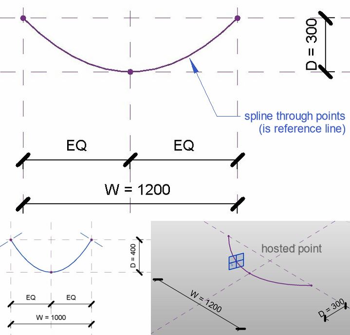


Load this into a Conceptual Mass family. Note the grey background and 3d work planes. You are in Point World.  Place 3 points, select them and choose, spline through points. You get something very much like a catenary. If you move any of these points the curve will adapt. They are “Driving Points”.  Now add more points to the line. These will be hosted points and their positions on the line are given by a parameter between 0 and 1 (Normalised Curve Parameter)  We need one in the middle and one close to each end. You can make the work planes visible (show work planes always)


Set the current work plane to one of these and place a profile on the point. You might have to rotate it 90 degrees.   For the GM profile to work in this context you need to reset two checkbox parameters from their default positions.  (Work Plane Based, & Not Always Vertical)  You may have a noticed that I initially had the Radius as a Type Parameter, so I had to change this also.  I have a little trick I like to use.  Place one point, and add a profile.  Select both and copy multiple into empty space.  Select the new points and “pick host”  I find it less tedious than repeatedly going “show reference planes always”, “set work plane” and “place instance”


Big profile in the middle, small ones at each end.  Select the 3 profiles and the spline, then hit “create form“  The result is pretty much a festoon, and it’s a surface. You can select this surface and divide it, then use those divisions to apply a pattern.


I tried the half step pattern and quickly realised that the results were not symmetrical. So best make one half of the festoon, export to SAT, and use two mirrored copies of the results.


The curtain panel family gave me some trouble. New family and choose Curtain Panel by Pattern. Select the grid and choose the type that matches your divided surface. Half Step has 6 points and 6 reference lines.


These families are supposed to keep your design intent even when they are twisted and bent to fit around a surface. So one of the tricks is to host a point on a point and give it an offset. Every point has 3 work planes (XYZ) so you have to set work plane before placing the point. The offset will push it out at right angles to this plane, depending where the point lies on a curved surface.


When I loaded my half-step panel into the surface it kept breaking so I reverted to a square grid. Finally I got some geometry to form... Looked more like a porcupine.


The curtain panels will all be different sizes, so the trick is to use a reporting parameter to drive the offsets. Something strange about this though. The values are much higher than expected. I introduced a global scale factor to adjust all the offsets with one type parameter and just tweaked until it looked right.


Eventually I settled on a panel that’s a blend between two segmental profiles. There are 3 offset  parameters, all calculated a reporting parameter which measures the width of each panel instance. I can’t understand why these offsets would be affected by the straightness of the path that the blend follows (all other things being equal)  


Maybe it’s a bug.  Or maybe I have done something weird with the reporting parameter.  Anyway, my workaround of inserting a type factor into all three equations was simple and effective.


Export to SAT and bring that back into an ordinary GM template. Add a few revolves and it’s looking half decent.  Maybe the tassles are a bit oversized in relation to the central garland.


I need a straight piece hanging down. This was pretty easy. “Save as”, the curved garland and push the middle point into line with the two ends. As discussed above, the panels become very flat. Still don’t understand that but it was simply fixed using the global scale factor “F”.


I intended to open the SAT export in 2014, scale it down a bit, explode and bring back to 2018. (This is partly about applying materials.)  


Sadly some of the panels dropped out on exploding.  So I tried another strategy.

Give the festoon a base plate to sit on, then go to a left side view and rotate the straight garland a bit so the two side rows get buried in the base. Ultimately I should go back and rebuild the massing family, reduce the width of the profiles and number of rows, the re export. But for now this works as a quick fix


Been a while since I fired up Enscape3d. Still working fine, and I fiddled about with Pixlr to come up with the final image.


Already I generated two different curved garlands plus a straight one. Once you have a concept set up in Point World creating variations on a theme is child’s play. Probably need to explore some different curtain panels next. Maybe an attempt at an oak leaf?

In conclusion, recapturing my pumpkin skills could be another way to approach some of those tricky classical motifs. Stay tuned: more to come.


Sunday, October 27, 2013

HAND ME DOWNS

Truth is, I'm running out of time.  Have to be ruthless now, try not to get flustered.  The familiar feeling of having bitten off a little too much.


I have to attach the hands/feet/paws/claws/hooves/wings to the ends of the limbs.  We have a rung, let's host another point on it, ultimately this can be controlled by the existing ankle position parameter, but for the moment let's keep it slightly away so we can see what we are doing


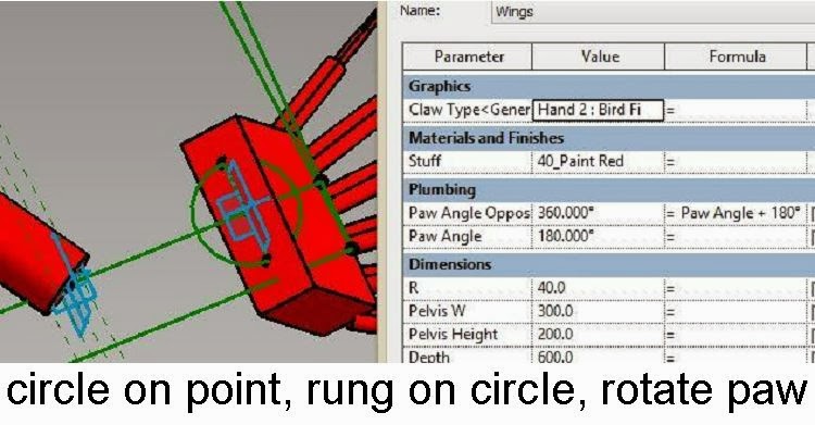
The point itself has a built in rotation parameter but that will only rotate us around the rung.  So let's place a circle on one of the planes, hang a rung across this and attach the paw.


That's effective enough, but I'm getting worried about controlling all these knuckle positions.


So I decide to rationalise my rig once more.  Two boxes that share an edge.  One diagonal rung, one curved rung.


I think this is probably the right level of simplification


So here is my assembled human.  Just call me Dr Frankenstein.  The rotation parameters come in useful to get the feet pointing forwards.  (always useful in my experience)


Can't get by without a cow and a chicken ...  & if you think there's some text missing in the picture above ... tick,tock ... got to keep going, can't worry about minor details.


I opt for setting up the limb pairs as types within the nested family and having a parameter to load the appropriate type. Working hard on getting my parameters linked up and grouped.


Here are the parameters for a limb-pair.  The left & right paws have separate angle controls. Best I could manage in the time available.


Ant the parameters for the master "Tetrapod" family.  Not yet reached the point where it is fully scalable.


And it is getting a little messy.  Some unpredictable errors popping up at times


I opt for the double nested planting trick to get my families to scale.  I need to move on.


All this nesting and parameter linking is taking it's toll.  Once you have the types set up everything is fine.  You can copy them around and navigate freely.  But when modifying a type or creating a new one it get's REALLY SLOW. Sit and wait for a minute or more while Revit thinks.  I checked out Task Manager.  No problem with RAM.  (actually it's still a pretty small family)  But the CPU has hit a plateau around 20%.  I am guessing that this has to do with Revit not multi-threading and basically my processing power is stretched to the limit. 1 core breaking out a sweat while the others sit back and have a cup of tea


Let's add a tail.  That would be another box rig.  Maybe I am being a bit willful with the rung placement, but actually there is a method to my madness.  The attachment end needs to be relatively square on, while the rest of tail should seem to curve freely in 3d space.


I used elliptical profiles once more.  Need a visibility parameter so as not to embarass my tail-free specimens


We are getting within a week or so of the present now.  (I am reaching the end of my tail)  The intention was to use a circle of beasties to reinterpret one Escher's common themes - metamorphosis.  Animals that come to life out of the paper, oozing out of a tessalated flat sheet into the real world.  Sadly I may not have time to do this one convincingly.


But I will lay down a tesselated floor down for my beasties to dance around on.  Pull out the generic model family from way back.  Nest it into a hexagonal curtain panel by pattern.  Six instances required.  I'm not going to try to make this resizable just now,


Load this into a divided surface.  Make use of a bit of trial and error adjustment to the U & V grid sizes


Hey presto, we have an infinite tesselated plane


Now the Escher work I have in mind has a dodecahedron, maybe a paperweight, sitting on the table.  One of a number of objects that the lizards clamber over on their way to paper space and back

He used polyhedra other regular geometrical solids in several of his works.  So I set myself the challenge of making something a bit like a cuboctohedron in Vanilla Revit.


It was moderately successful and quite parametric.  Several variants possible and it resizes too.


In one of its configurations it comes pretty close to being a close-packing solid.


Would have loved to spend more time playing with this aspect, but we really must get back to the "END PRODUCT"  Which at the moment is 3 Escheresque images.  The infinite fish piece is finished.  But the other 2 need a good deal more attention.  Let's start with the Still Life Street.  The books were looking a bit blank & I got the idea of making a halloween connection via their titles.  Why not use Philip Chan's trick of the face-based model text family that cuts into another.

Interesting thing about hosted families, even though the host inside the family is just a "stand-in" it's size has a limiting effect.  If you want to make a really big door or window, you may need to stretch the wall inside the family so that there is still something left.

I was very puzzled when I first came across this.  You make a window that works fine for ages and ages, then suddenly you decide to make a really big one and everything goes wrong.  I suppose you could lock the wall to ref planes so that it automatically grows with the opening.

I had this same issue with a face based family for placing grooved titles on my book covers.


It's a face-based family with model text that is inset into the extrusion.  Use "cut" and have a parameter to turn off the text.


I also made a face-based family that cuts a rectangular groove of variable size.  This allows me to paint panels in the book covers with different materials.


Add a few bits and pieces from my various adventures and give it a render.  Layer things up in Sketchbook to enhance the image.  And finally back to Another World to do the same kind of thing.


I spent my last available weekend writing up these two mammoth posts and further embellishing these two "impossible worlds"  I had hoped to also tackle the circle of beasties/tesselation idea, but time ran out on me.

So just one post to go.   Tomorrow I will present my final images, clean up the files a bit, upload a package and reflect a little on my successes & failures.

Thursday, July 25, 2013

SAY CHEESE

Smile.  Some quick images following on from yesterday.

The topic is curtain panels that scale automatically.  The restrictions are you have to keep to the original proportions and the curtain wall must be a whole number of panels in both directions.

The advantages are : changing sizes on the fly even with complex geometry.  Take the following "swiss cheese" example.


You could make this without the double-nested planting families.  And you could edit the extrusion sketch manually, scale it down, save as a different name, reload into project.  It would only take a few minutes, but it's a less fluent way of working.  I'm backing the double-nested technique for situations where you want to play around with the size on the fly, experiment with design ideas quickly.

The next one is similar.

 
I guess you could even make this one parametric, but it would hardly be worth the effort.  Double-nesting is easy once you've set up the first panel and linked up the parameters the way you want them.  This is more of a tool for designers than documenters IMHO.

The speed advantage becomes much greater once you progress beyond a single extrusion.  The next example would be a real pain to resize multiple times by conventional methods.


Using double-nesting I created all three examples from scratch, including rendering and image processing in a couple of hours last night.  I only set up 3 different sizes for each panel design, because that's what I reckoned would show up clearly in a single image.  I could easily have created 10 different sizes for each though in a matter of minutes.

I have more on this.  Some egg & dart mouldings for Paul to salivate over :-) but that will have to be on Sunday.  Right now it's way past home time on a thursday afternoon, it being Ramadan and all.  So time to hit the weekend here in the Gulf.  Enjoy the cheesy designs everyone.


Thursday, June 27, 2013

LUMPY DIAGRID

Almost 2 years ago now I attempted to make a big lumpy diagrad roof surface.  Very large scale structure, shades of Bucky Fuller.  Shades is right because it was essentially an enormous shade structure.


I got stuck at some point and since this was an inquiry "after the fact" it's been sitting neglected ever since.  It related to a quick competition entry & the inquiry was basically, could we have done this more easily using Revit ?  One of the interesting things here is the realisation that 2 years ago I was floundering about as far as conceptual massing was concerned.  The big breakthrough for me came with the first pumkin competition a few months after this initial failed attempt.  So I decided to take another shot.


My first instinct was to make a rippled rectangular surface and cut off the edges with voids.  That didn't work.  Or rather it seemed to be working until I divided the surface.  Then it just ignored the voids & reverted to dividing the full rectangle.  (SEE ALFREDO'S COMMENT below, pointing out that it IS possible to select the inner surface, you just have to KEEP ON TABBING)


I found that I could bring the surface into a project and use curtain system by face.  But that only allows me to use rectangular panels.  I wanted a rhomboid. So I decided to drop the void idea and try to make the surface directly.  ie a lumpy-bumpy surface with a smooth irregular outline.


This turned out to be fairly easy, in principle at least.  Just a series of splines like before, but instead of lining the ends up, let them move in and out with the boundary curve.  Make the first and last curve shorter and push the mid-points out so that the curve in plan.  With a bit of pushing and pulling you can create something with flowing curves in both plan & elevation.


Now for the next problem.  The divided surface distorts to in response to the irregular border.  Not to worry, divide by intersects to the rescue.


This takes a little while to set up.  Lots of reference planes.  But it works.  So let's try to build something closer to the original shape.


I quite enjoyed using this method for defining a surface on the second time around.  The curves are simpler and I'm getting better at bending the shape to my will.  I didn't get around to setting all the intersect planes up though.  Time ran out on me.


Maybe that's just as well, because when I started on this little write-up it struck me that my surface cut by voids might be solved by having a solid cut by voids.  In other words, take the open ended splines and box them out so they each form a closed loop.  Now when I select these and create form I get a solid block with a wavy top surface.  Cut this with the voids I made before.  Now I can select the top surface and divide it.  Works fine.


This is preferable to the intersects method.  I can play around with the density and angles of the rhomboid grid just by varying the U & V values.  Also, changing the boundary shape in plan is going to be simpler.  What is more, I suddenly realise that I can use loaded profiles threaded on a spline for the solid.  Pumpkin take 2 comes into play.  Organic form and all that.

So I make a profile by my usual points method, building in a bit of parametrics.


Set up a spline for the backbone of the whale, or maybe it's some kind of a manta-ray type beastie.


Thread the profiles along.  And make a form.  Tweak it a bit.  Looking good.


Go into plan view and set up the reference line loops for my 2 voids.  Make them as solids first, then switch to void and cut geometry.  Nice.

Now tab-select to get the surface.  Divide it.  Interesting how the grid lines follow the curvature of the backbone.  Switch to romboid & tweak the U V values.  Load up a panel and we're in business.


So what did I learn ?


  • You can trim a surface to shape, but when you try to divide it ... it reverts to the original.
  • You can model a surface directly with smooth flowing edges, but when you divide it the grid will follow the  edges.
  • To place an even grid over an amoeba-like form, make solid geometry & tab select a surface to divide.  The more rectangular the original shape (before edge cutting) the more regular the divided grid.


and finally :  Keep trying because there is a way to get the effect you are looking for.