Thursday, June 27, 2013

LUMPY DIAGRID

Almost 2 years ago now I attempted to make a big lumpy diagrad roof surface.  Very large scale structure, shades of Bucky Fuller.  Shades is right because it was essentially an enormous shade structure.


I got stuck at some point and since this was an inquiry "after the fact" it's been sitting neglected ever since.  It related to a quick competition entry & the inquiry was basically, could we have done this more easily using Revit ?  One of the interesting things here is the realisation that 2 years ago I was floundering about as far as conceptual massing was concerned.  The big breakthrough for me came with the first pumkin competition a few months after this initial failed attempt.  So I decided to take another shot.


My first instinct was to make a rippled rectangular surface and cut off the edges with voids.  That didn't work.  Or rather it seemed to be working until I divided the surface.  Then it just ignored the voids & reverted to dividing the full rectangle.  (SEE ALFREDO'S COMMENT below, pointing out that it IS possible to select the inner surface, you just have to KEEP ON TABBING)


I found that I could bring the surface into a project and use curtain system by face.  But that only allows me to use rectangular panels.  I wanted a rhomboid. So I decided to drop the void idea and try to make the surface directly.  ie a lumpy-bumpy surface with a smooth irregular outline.


This turned out to be fairly easy, in principle at least.  Just a series of splines like before, but instead of lining the ends up, let them move in and out with the boundary curve.  Make the first and last curve shorter and push the mid-points out so that the curve in plan.  With a bit of pushing and pulling you can create something with flowing curves in both plan & elevation.


Now for the next problem.  The divided surface distorts to in response to the irregular border.  Not to worry, divide by intersects to the rescue.


This takes a little while to set up.  Lots of reference planes.  But it works.  So let's try to build something closer to the original shape.


I quite enjoyed using this method for defining a surface on the second time around.  The curves are simpler and I'm getting better at bending the shape to my will.  I didn't get around to setting all the intersect planes up though.  Time ran out on me.


Maybe that's just as well, because when I started on this little write-up it struck me that my surface cut by voids might be solved by having a solid cut by voids.  In other words, take the open ended splines and box them out so they each form a closed loop.  Now when I select these and create form I get a solid block with a wavy top surface.  Cut this with the voids I made before.  Now I can select the top surface and divide it.  Works fine.


This is preferable to the intersects method.  I can play around with the density and angles of the rhomboid grid just by varying the U & V values.  Also, changing the boundary shape in plan is going to be simpler.  What is more, I suddenly realise that I can use loaded profiles threaded on a spline for the solid.  Pumpkin take 2 comes into play.  Organic form and all that.

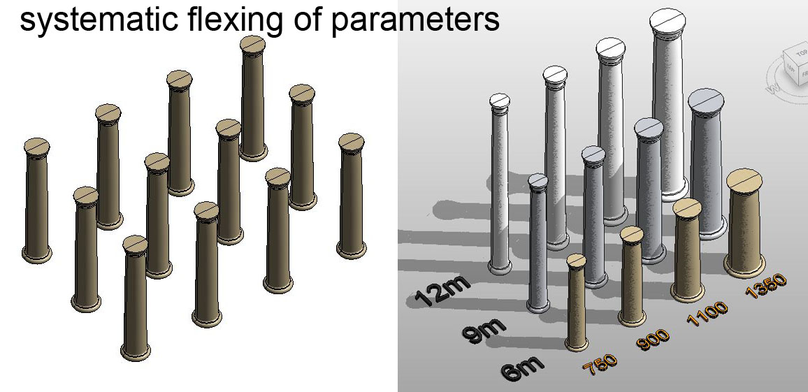
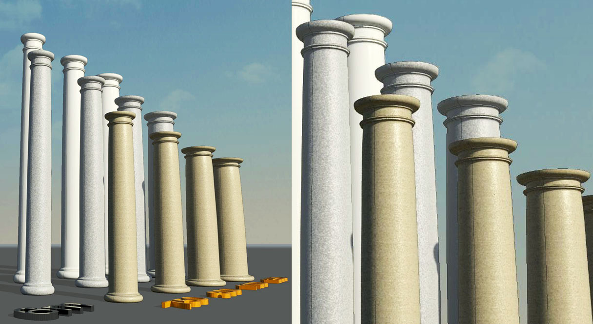
So I make a profile by my usual points method, building in a bit of parametrics.


Set up a spline for the backbone of the whale, or maybe it's some kind of a manta-ray type beastie.


Thread the profiles along.  And make a form.  Tweak it a bit.  Looking good.


Go into plan view and set up the reference line loops for my 2 voids.  Make them as solids first, then switch to void and cut geometry.  Nice.

Now tab-select to get the surface.  Divide it.  Interesting how the grid lines follow the curvature of the backbone.  Switch to romboid & tweak the U V values.  Load up a panel and we're in business.


So what did I learn ?


  • You can trim a surface to shape, but when you try to divide it ... it reverts to the original.
  • You can model a surface directly with smooth flowing edges, but when you divide it the grid will follow the  edges.
  • To place an even grid over an amoeba-like form, make solid geometry & tab select a surface to divide.  The more rectangular the original shape (before edge cutting) the more regular the divided grid.


and finally :  Keep trying because there is a way to get the effect you are looking for.


Monday, June 24, 2013

SPIRAL RIGGING

I have written many times about the "scalable rectangular rig" (SRR) This is a device for use within the conceptual massing enviroment which I find to be extremely useful.  With it, you can apply 2 parameters to control the scale & proportion of an element, thereby achieving a great deal of variation very simply.


This can be compared to the age-old artists trick used to guide the eye and hand when scaling up (or down) an image.  Alberti used a rectangular grid on a pane of glass to guide his transcription of nature on to a canvas marked out with a similar grid.  I have no doubt that Michealangelo used the same method in reverse to scale up his sketches onto the surfaces of the Sistine Chapel ceiling.


I first used this method to when threading profiles onto a spline.  The spline itself is hosted on a "ladder" within the rectangle.  The width factor allows you to vary the curvature of the spline.  Subtle variations in size and proportions are characteristic of the natural world.  We used to call this organic form.  Today it is fashionable to speak of biomimicry.


D'Arcy Thomson was a biologist/mathematician who looms large in any discussion of organic form.  His book "On Growth & Form" influenced may architects & in it he used grids to illustrate the effects of proportional changes on biological form.


A variation on the SRR replaces the scale factor with 2 adaptive points.  The result is a 2-pick component which will adapt itself to the points of attachment.  Used with divide & repeat this opens up a wide range of possibilities.  I typically use a scenario where we imagine ourselves as Oscar Niemeyer exploring variations on an idea for a cathedral at Brasilia.


The spline within an SRR can also be used to create a revolve.  I first used this for an avocado pear, but more recently I devised a "form-finding" demonstration based on the gherkin to show how a wide variety of curves can be generated based on 3 or 4 variables.


All this is by way of background.  Since I returned from RTC Auckland I have begun to experiment with circular rigs.  These lack the "width factor" element, but have other interesting properties.  Today I want to look at spirals.


Start with a "Generic Model Adaptive" template.  Go to a plan view.  Make a circle (reference line)  Give it a radius parameter "R".  Now draw a series of spokes from the centre point to the circumference, check "3d snapping" so that the ends are defined by nice black dots (reference points)  Make sure you always draw from the centre outwards.  Select all the points on the circumference and change the measurement type from NCP (normalised curve parameter) to Angle.  Use these angle settings to space the points equally around the circle.


It's quite easy to thread a spiral around the spokes, just working "freehand" to guess the curve.  I used spline through points which automatically operates as if 3d snapping and chain were checked.  Change the radius to reassure yourself that the whole thing will scale up & down proportionately.


Now we just have to add precision & control ... plus some solid geometry that will show up in a project.  It gets a bit tedious now (as in repetitive)   Give each point a number (under name) this will reduce the potential for confusion.   Then next to the NCP value, click on the little parameter button & give each point an instance parameter.  Set point 1 to NCP_01, point 2 to NCP_02 etc.   It does help to use the zero before the first 9 and to be systematic.  It can be quite confusing if the parameter list is out of sequence.  Try to get a rhythm going: name the point, add parameter, name it (you can use copy-paste and change the last digit), change to instance.


Next, create a number parameter called F (factor)  you could also call it X if you like, doesn't matter.  Set the value of F to one more than the number of points in your spiral.  Now feed in formulae for the position of each point.   F/(point no)  All this does is to divide the length of each spoke into small equal lengths and step each point outwards by one of these divisions.  I create more divisions than points so that the last point will fall short of the circle.  Just in case I want to select it won't be confused with the point at the very end of the spoke.


You have created a geometric spiral.  It's the kind of spiral you get when you coil a rope around on the deck of a ship.  All the coils are spaced the same distance apart.  You really need quite a lot of points to make a good geometric spiral because you want to go around the circle at least 4 times.  I've been using 12 spokes.  You could try using 8, but I think you will find that the spiral distorts, especially at the ends.


Most organic spirals are logarithmic.  The distance between the coils expands as you go around.  Think of a snail shell.  You can think of it in terms of a graph.  When the distances out from the centre increase by equal steps, that will be a straight line graph.  Clearly the logarithmic spiral will give a curved graph.  But we want to have the same start & end points (zero to one)  Because that's the range we have available using NCP.  Basic maths suggest we need to square something to get a logarithmic curve.  Square of zero is zero, square of one is one.  So we can square the whole thing & the formula for point 3 will look like this   (F/3)^2


Make a second copy of your family and go methodically down the formulae, converting them to squared versions.  Now you have two spiral families, one geometric & one logarithmic.


To create geometry we need two points hosted on the spiral, one close to each end.  There are 2 reasons for keeping them away from the ends.  Firstly so they are easier to select, secondly the spline distorts a little at its open end.  The last part tends to straighten out just because there isn't another point pulling it back in towards the centre.


Place your points, make the workplane visible, place a profile on it.  I have a few ready-made mass profiles sitting in a folder just waiting to be used.  There are a bunch of them in my entry for last year's pumpkin competition.  You can find them under downloads.

Link their radii to instance parameters.  You need to make the inner one quite small.  Select both profiles plus the spiral and create form.  If it refuses, try a smaller radius.

I want to have the two profiles scale up with the radius of the whole spiral.  So I use a little formula.  I called my two profile sizes P1 & P2.  Create number parameters X1 & X2

P1 = R / X1,  P2 = R / X2


If you made everything with instance parameters, you can place a few of these families in a project and play with the variations.  Scaling is easy.  Just type in a radius and the whole thing scales proportionately.  Vary the values of X1 & X2 to make the geometry thinner or fatter, more or less tapered.

One nice bonus is the ability to adjust the value of F.  If you try to make is smaller the family will break, but if you make it bigger, the spiral will tighten up.  Think of it this way.  The outer end of the spiral is sitting at 25/26 of the spoke length.  Almost at the end.  If you increase F to say 50, it will move to 25/50.  That's half way.  The effect will be even more dramatic for the logarithmic spiral.  Make small adjustments.  The geometry will fail if it becomes self-intersecting.  So if you want a really tight spiral you will have to creep up on it slowly.

It's quite easy to add an extra turn to your spiral.  Just add 2 points on the next 2 spokes, select the spiral, control-select the points, hit spline through points.  Repeat until you reach the length you want.  Number the points.  Add NCP parameters.  Fill out the formulae.


I went on to play around with rectangular profiles a little.  But by now I'm starting to wonder what the applications are.  Sort of looks like wrought iron scroll-work but do you really want to get into heavy conceptual massing studies for a garden gate ?  I guess you could imagine designing a water feature or similar landscape element this way.

Whatever.  I had fun & kept my brain busy.  If you want to play around with it you can download a couple of the families I made.  Don't look too closely at the parameter names etc, they are just as they came out during my explorations.

spiral families


Monday, June 17, 2013

SPIKEY STUFF

SPIKEY STUFF

I posted about this way back.  

http://grevity.blogspot.ae/2012/03/more-bermuda-triangles.html

http://grevity.blogspot.ae/2012/03/drawing-curtain.html

Spikey geometry is generally easier to make in sketchup than directly in conceptual massing.  If anyone has the answer to doing it in Revit, please share, because I have failed.  You can go so far, then you get stuck.  Revit massing loves nurbs surfaces & curvy blends.  Sketchup can't do that, has to fake curves with a smoothing algorithm, because what it really loves are triangles.  It makes meshes.

Revit topography is a mesh, but just about everything else is solid geometry.  The interesting thing is that it can take a Sketchup mesh & convert it into a solid ... within limits.  For example, make an extrusion in Sketchup.  Draw a couple of diagonals on faces. Push & pull a bit.  Save.  Now open Revit.  Make an in-place mass (or an external mass family)  Import the skp file into the mass.  Finish mass.  Make mass floors.  It works.


But if you carry on playing around, pushing & pulling, triangulating & twisting: at some point it will break.  Then you get the dreaded message as you finish the mass: "... contains only mesh geometry ... can't be used to compute Mass Floors ..."  End of story.


A year ago I failed to find a way around this. Then I was thinking about some work that Jerome Buckwell & Liam Carey presented in Auckland.  They have been exploring workflows between Sketchup & Revit for concept design with considerable success.  I hope they will forgive me for including a low-res snippet from their presentation here.  It's a bit different from what I was attempting, but it got me to thinking.


If you load the Sketchup file as a link, you can keep both applications open.  Make a few changes in skp, save, reload in Revit.  If no error, carry on.  If error, backtrack & try again.


Bear in mind that my skp skills vanished about a decade ago. But gradually I found that I was evading the error message as I cycled through the process repeatedly


Just to demonstrate that Revit converts the mesh into a true solid I changed the cut pattern of the material to solid red.  Section box cuts through just as if it were standard Revit geometry.


Using this method I managed to develop quite a complex form while keeping mass floors alive.  It would be better if I had some clear rules as to what causes the "can't compute" error.  But for the meantime the "baby steps cycle" provides a workaround.


Thursday, June 13, 2013

MORE PANCAKE PEOPLE

I came across the comment below yesterday on Mark Cronin's blog   It seemed quite appropriate.  It's easy to get carried away with being "clever" & pushing the boundaries. but ultimately the success of BIM hinges on what hundreds of thousands of ordinary guys & gals can do with it out there in the construction industry.


One thing that experienced users with a public presence can do is to create better content and make it freely available.  So in this spirit, I return to the world of entourage.  If you go to my post FLAT PEOPLE & scroll down to the end, you will see that I promised to make another 15 ... IF 2 of my readers made a collection of their own available.  Exactly 2 generous souls responded to this challenge.  You can find their links under comments, and expand your entourage options with two excellent downloads.


I set about making my next batch by asking a colleague to export some sketchup people to CAD, as pickable outlines.  This kind of worked, but sadly "TAB-pick" failed.  I was faced with a rather tedious session of mouse clicking.  I could have just thrown sketchup files into Revit families, but this makes the changing of materials a bit more cumbersome and sometimes impossible.  Better quality Pancake People means native Revit geometry, so I manned up and set myself to picking.


Every cloud has a silver lining.  You have to think of something while doing a repetitive task, and I found myself reflecting on what makes for a good Entourage object.  It was obvious that different people had been involved in the original tracing exercise.  It may seem strange to talk about style & panache when referring to tracing an outline using a mouse to create short line segments, but as I proceeded, I found myself looking for figures that had been traced with a certain freedom & economy of means.  It's more effective to vary the line length and sometimes to exaggerate the changes in direction slightly to emphasise folds in cloth (for example).


Also I prefer to have my people standing firmly on the ground.  Some of the figures out there look fine in perspective view, but pretty stupid in elevation.  Perhaps this is because Sketchup doesn't feature true orthographic (one of the reasons it's not really BIM)  Then I get to thinking, "why are we taking this cardboard modelling software as the standard to aim for when it comes to people & trees & furniture ?"   There is a reason.   It's much easier to find good looking objects of these categories if you live in Skup-World.  But that doesn't mean we have to copy mindlessly.  Rise to the challenge & think about what you are doing.


Soon enough I had my first 9 persons.  Then I realised I was seriously short of Arabic people.  Time to exit Skup-Copy mode and trace directly from images.  This was another eye-opener.  If you grew up drawing freehand, as I did, you know that when it comes to people, it's all in  the hands & faces.  Mindlessly tracing hands & faces from photographs is a recipe for disaster.  You have to have some experience, and you need to stop and look at the end product and make some critical adjustments based on what your eyes tell you.  This is where the shape arrows on a Revit extrusion come in really handy.  You can make tiny adjustments to the lips & nose working directly on the extrusion.  Tweak, assess, tweak, assess.  Am I being silly ?  It's only a stylised person to throw around your project to give scale.  Oh really ?  Not to me.  We design by creating images that catch the vision that is in our imagination.  Stylisation & abstraction are thousands of years old.  For most people the effect may be subconscious, but we live in a world of visual imagery, and small details count.


Anyway I went on to create 6 entourage objects based on people wearing the national dress of the Gulf Region where I live & work.  I'm not claiming them as great works of art, but I was focussing on the kind of issues I would have been thinking about if I had been drawing with a pencil.  This brings me to my final point.  It's useful to think about tips & tricks for Revit and it's good to extend the art of the possible BUT we should also strive to treat Revit like a pencil.  Just pick it up, let it become one with your hand, eye & brain, thinking about the vision you are trying to capture.  Let the tools become transparent.  Create.

NEW COLLECTION

Oh & if anyone else wants to contribute ... that would be nice!

Wednesday, June 5, 2013

TUSCAN RIG

I'm not sure if it's jetlag or severe OCD, but I woke at the crack of dawn this morning with Tuscan columns & rectangular scalable rigs on my mind.  Let's be generous and call it a Eureka moment.  Not sure why this didn't occur to me earlier, but it is possible to use a rectangular rig to solve the scalable Tuscan dilemma.

New family - Generic Model Adaptive.  Make a rectangular rig in an elevation view.  Or just download this starter file . . .                  Rectangular Rig


The rig is set up in front elevation, so bring in a suitable jpeg and scale it to an appropriate size.  Mine happens to be six metres high and I set the width of the rig to 750, which seemed to be about right.  The next part is a bit tedious, but I had it all done by breakfast time.  Actually it's just 6.15 am as I type these words and I'm expecting the alarm to go off at any moment.

Set 3d snapping on and chain off.  Now you can created lots and lots of horizontal "rungs".  I ended up with around 25 or 26.  With a bit of practice you can draw these so that they snap to horizontal (most of the time) but don't worry if you get that "slightly out of alignment" message.  They don't actually have to be horizontal for the method to work, although it does give us an unexpected bonus later on as you will see.  The alarm is getting annoying so I will have to finish this off later.


2 fried eggs, a shave & a mad dash down Emirates Highway.  I'm in the office now and it's only 7.30 so let's continue.  Once you have some rungs in place you can start hanging splines on them.  Some of them can be drawn directly, the straight bits might be better created by selecting 2 points and doing a "spline through points".  The hardest parts to do are the straight segments with a bit of a curve on the end.  Splines are very interactive.  Push down on one part of the curve and another part will shoot up.  With a few extra points and a bit of practice you can get pretty close.


After I had done most of the capital I decided to test it out.  Just selected the spline and did a "create form"  The result is a surface and it looks pretty good to me, so on we go.

Actually I was past half way by this stage.  ie Most of the complexity in a tuscan column resides in the capital.  By the way you may notice that I did a "duplicate view" so that I had a front elevation without the jpeg.  This makes it easier to select points & see what you are doing.  (I'm still using 2013 by the way)  To complete the profile for the revolve you need to draw reference lines on top of reference lines.  This is always trick.  I wish we had subcategories of reference lines so I could have 2 types with different colours.  You can always use the sunglasses & do a temporary hide of the rig.  Anyway next thing you know I have a Tuscan column.  Looks pretty good, except for the seam.  That's one drawback with the conceptual massing revolves, they always come in 2 halves.  That's a real shame.


Took it into a project and the elevation view looks fine.  None of the artefacts we got with the "scale by spline" in vanilla Revit.  And because I took the time to get the ref lines horizontal I can get a dimension chain to pick them up.  Just do a callout and up the scale to 1:10 and we have all the dimensions my mould maker might need.


So the next step was to lay out a whole array of these things, make sure the parameters for Height & Width (actually the Width is more like a radius, it's the width of the rectangular rig, which is actually a bit more than the radius at the base of the column)  then we can vary the size of this array in a systematic manner.  I'm pretty chuffed with this result, BUT ... let's not get too carried away.


I decided to do a camera view.  Now this is where I start moaning about why we can't navigate through Revit in perspective.  Yeah, yeah, yeah ... But it is clear that errors of proportion are much more obvious in a camera shot.  Now all the columns I would be happy to use in real life, (the ones that are not ridiculously thin or disgustingly fat) are pretty good, but at the extreme ends of the scale the mouldings look wrong.  Seems to me that we should probably be making this column in 3 parts so that the width factor for base & capital can be controlled independently of the width factor for the shaft.


That will have to be for another day because it's 5 to 8 now and work beckons.  I will aim to tidy up this post at lunch time and toss it out there before leaving tonight, because tomorrow is an islamic holiday & our weekend is friday/saturday so ... LONG WEEKEND COMING.