Park Guell sits in a horseshoe shaped basin nestled into the foothills of the mountains behind Barcelona. At 148m above sea level, the main terrace has stunning views over the city and out to sea. How to get this into my Revit model ? Can I grab contours from Google Earth ?

A quick search throws up references in Revit Forum and CAD addict, two excellent sources of information. There is a plug-in for AutoCAD available as a free download on Autodesk LABS. This creates a mesh. Save to DWG, link into Revit and create topography by import instance: click, tick, done.

This is wonderful, but I want to see trees and houses, and those wonderful elevated roadways that snake around the folds of the hills, supported on random stone pillars. vaults and buttresses in trademark Gaudi style. As you can see I was successful. The challenge was to create a material from Google Earth imagery, scale it correctly, and map it onto the topography.

If you switch to realistic view in AutoCAD, you will see that the mesh already has a low-res image draped over the terrain. This is useful. I can inspect the corners carefully to decide where to crop my image. The image itself comes from Google Earth Pro which allows you to save at higher resolutions. If you only have the free version that's fine, the results will still be useable.

My aim is to create a Russian Doll effect. A site, within a site, within a site. The inner portion will be fully modelled in Revit. The next shell will be fairly high resolution topography and imagery. As we proceed outwards the resolution will necessarily become coarser. No problem. All I need is the impression of the city spreading out over the coastal plain with the sea shimmering out on the horizon.
My Russian dolls are linked Revit files with shared coordinates and levels. The main file, is modelled directly in Revit. There is no imagery mapped onto the topography here. Instead I have subregions with materials for grass, footpaths, etc. This is topo 1.

Topo 2 is a linked Revit file with a larger rectangle of topography. I have carefully cropped an image to match the rectangle that was grabbed by the Autocad Plug-in, and set up a plan view that allows me to decide on the real-world size of this "rectangle" ... which is actually somewhat distorted as it wraps over the contours.

Next step is to create a material based on the cropped image and scale it up to life size. For some crazy reason I had to mirror all my images (rotate canvas, flip horizontal in Photoshop) It's almost as if the topography turns itself inside out during the "create from import instance" process. Also had to rotate 90 in most cases and to adjust the X & Y offsets. If you are not familiar with these features in appearance tab of the materials dialogue, now is a good time to explore. They are hidden in a secret room, accessed by clicking on the image. To choose a new image you have to click on its name. It's easy once you know how.

Be aware that the mesh is quite crude. If you are a real architect doing a real job for a real client ... better get a real survey done by a real land surveyor. But for early concept work, (or explorations into Gaudi) it's certainly much better than guess work.

I decided to record some levels and coordinates from Google Earth to check against my Revit model. This is all useful information when it comes to setting up a shared coordinates and levels system. My first attempts to creat meshes were incorrectly scaled. Need to set units in both Google Earth and AutoCAD, then check the results before moving on,
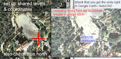
It is well known that Revit hates DWG style Real World Coordinates. You have to accept centre-to-centre imports. I am sure many of you have struggled with this. In this case the DWG files are Revit friendly if you accept the default values when creating the mesh (enter, enter = place at 0,0 with zero rotation) Vertical heights will be correct, but to locate X & Y you will need Northings and Eastings for a known feature.

In practice this meant some manual adjustment when linking Topo 1 into Topo 2 (for example) Once you have linked any 2 files together and shared coordinates, you are in business. You can now link any 2 files by shared coordinates, load and unload at your pleasure. Once again, if you are not too familiar with shared coordinates yet, get your hands dirty. Experiment and learn. It may seem hard at first, but it's wonderful, powerful stuff "once you know how".

One problem with multiple nested sites is going to be 3 sets of topography in the same place. The larger pieces are extremely crude and will obscure the more detailed modelling of the smaller ones. My solution is to create resizeable holes: voids that allow the Russian Dolls to sit inside each other. Resizeable is especially important in the middle because I want to gradually eliminate the crude Google Earth topograhy as I replace it with Revit objects. What do you call a resizeable hole in Revit topography ? Yes, it's a pad.

If you check out some of my images you will see where Topo 1 and Topo 2 are weaving in and out of each other. I am gradually reducing this effect by editing topo 1, moving individual points up and down. It's all very ad-hoc, but in the absence of highly detailed survey information ... it works for me. I ended up with 4 topo surfaces, the biggest being almost 8km wide.

Don't know if anyone else has used this method, or can suggest improvements. At the moment I am quite excited by the potential. Can't wait to put Corb's chapel on its hill overlooking the village of Ronchamp and identify the paths that pilgrims take up the hill. When is a pilgrim not a pilgrim ? (think Tourist, but then maybe tourism is the modern form of pilgrimage. Worship the sun and the sand, the wilderness, the historic creations of past architects. Restore your soul with a journey to some metaphoric Canterbury)

And so my last image is of Gaudi's hypostyle hall at dawn with shafts of light streaming in to wake the oracle. And my oracle is telling me that there are many more mysteries to be uncovered at Park Guell if I have the patience and endurance to continue to model. So far my representations are as crude as topography I grabbed from Google Earth. There are so many avenues to be explored: wrought iron railings and gates, the gatehouses, the raised roadways, how to represent the broken tile patterns ? how to model the rough stone work ?

Behind it all the deeper issue of how to abstract something highly complex into a simpler version that is managable, recognisable and useful. It's sometimes called seeing the wood from the trees and it's "what Architects do."


A quick search throws up references in Revit Forum and CAD addict, two excellent sources of information. There is a plug-in for AutoCAD available as a free download on Autodesk LABS. This creates a mesh. Save to DWG, link into Revit and create topography by import instance: click, tick, done.

This is wonderful, but I want to see trees and houses, and those wonderful elevated roadways that snake around the folds of the hills, supported on random stone pillars. vaults and buttresses in trademark Gaudi style. As you can see I was successful. The challenge was to create a material from Google Earth imagery, scale it correctly, and map it onto the topography.

If you switch to realistic view in AutoCAD, you will see that the mesh already has a low-res image draped over the terrain. This is useful. I can inspect the corners carefully to decide where to crop my image. The image itself comes from Google Earth Pro which allows you to save at higher resolutions. If you only have the free version that's fine, the results will still be useable.

My aim is to create a Russian Doll effect. A site, within a site, within a site. The inner portion will be fully modelled in Revit. The next shell will be fairly high resolution topography and imagery. As we proceed outwards the resolution will necessarily become coarser. No problem. All I need is the impression of the city spreading out over the coastal plain with the sea shimmering out on the horizon.
My Russian dolls are linked Revit files with shared coordinates and levels. The main file, is modelled directly in Revit. There is no imagery mapped onto the topography here. Instead I have subregions with materials for grass, footpaths, etc. This is topo 1.

Topo 2 is a linked Revit file with a larger rectangle of topography. I have carefully cropped an image to match the rectangle that was grabbed by the Autocad Plug-in, and set up a plan view that allows me to decide on the real-world size of this "rectangle" ... which is actually somewhat distorted as it wraps over the contours.

Next step is to create a material based on the cropped image and scale it up to life size. For some crazy reason I had to mirror all my images (rotate canvas, flip horizontal in Photoshop) It's almost as if the topography turns itself inside out during the "create from import instance" process. Also had to rotate 90 in most cases and to adjust the X & Y offsets. If you are not familiar with these features in appearance tab of the materials dialogue, now is a good time to explore. They are hidden in a secret room, accessed by clicking on the image. To choose a new image you have to click on its name. It's easy once you know how.

Be aware that the mesh is quite crude. If you are a real architect doing a real job for a real client ... better get a real survey done by a real land surveyor. But for early concept work, (or explorations into Gaudi) it's certainly much better than guess work.

I decided to record some levels and coordinates from Google Earth to check against my Revit model. This is all useful information when it comes to setting up a shared coordinates and levels system. My first attempts to creat meshes were incorrectly scaled. Need to set units in both Google Earth and AutoCAD, then check the results before moving on,

It is well known that Revit hates DWG style Real World Coordinates. You have to accept centre-to-centre imports. I am sure many of you have struggled with this. In this case the DWG files are Revit friendly if you accept the default values when creating the mesh (enter, enter = place at 0,0 with zero rotation) Vertical heights will be correct, but to locate X & Y you will need Northings and Eastings for a known feature.

In practice this meant some manual adjustment when linking Topo 1 into Topo 2 (for example) Once you have linked any 2 files together and shared coordinates, you are in business. You can now link any 2 files by shared coordinates, load and unload at your pleasure. Once again, if you are not too familiar with shared coordinates yet, get your hands dirty. Experiment and learn. It may seem hard at first, but it's wonderful, powerful stuff "once you know how".

One problem with multiple nested sites is going to be 3 sets of topography in the same place. The larger pieces are extremely crude and will obscure the more detailed modelling of the smaller ones. My solution is to create resizeable holes: voids that allow the Russian Dolls to sit inside each other. Resizeable is especially important in the middle because I want to gradually eliminate the crude Google Earth topograhy as I replace it with Revit objects. What do you call a resizeable hole in Revit topography ? Yes, it's a pad.

If you check out some of my images you will see where Topo 1 and Topo 2 are weaving in and out of each other. I am gradually reducing this effect by editing topo 1, moving individual points up and down. It's all very ad-hoc, but in the absence of highly detailed survey information ... it works for me. I ended up with 4 topo surfaces, the biggest being almost 8km wide.

Don't know if anyone else has used this method, or can suggest improvements. At the moment I am quite excited by the potential. Can't wait to put Corb's chapel on its hill overlooking the village of Ronchamp and identify the paths that pilgrims take up the hill. When is a pilgrim not a pilgrim ? (think Tourist, but then maybe tourism is the modern form of pilgrimage. Worship the sun and the sand, the wilderness, the historic creations of past architects. Restore your soul with a journey to some metaphoric Canterbury)

And so my last image is of Gaudi's hypostyle hall at dawn with shafts of light streaming in to wake the oracle. And my oracle is telling me that there are many more mysteries to be uncovered at Park Guell if I have the patience and endurance to continue to model. So far my representations are as crude as topography I grabbed from Google Earth. There are so many avenues to be explored: wrought iron railings and gates, the gatehouses, the raised roadways, how to represent the broken tile patterns ? how to model the rough stone work ?

Behind it all the deeper issue of how to abstract something highly complex into a simpler version that is managable, recognisable and useful. It's sometimes called seeing the wood from the trees and it's "what Architects do."


