Sunday, March 31, 2019

COMING UP ROSIE


I wanted a quick challenge to occupy my attention for two or three hours before coming back to review and complete my last post.

I started by collecting images for my classical ornament collection. This is a small but growing corner of the “archive” that syncs between one drive and my two laptops.


I can access this on my phone, flip through images I have collected over the past 25 years, zoom in and clip out details with my S-pen. This allows me to stand up and take a break from the big screen while removing productive.


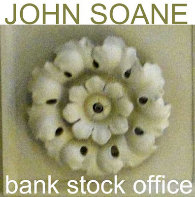
The rosette is a very common motif. It can be very simple, or it can rival the Corinthian capital in complexity. The one I chose is from the Bank Stock Office, used on curved ceiling soffits as a punctuation mark, dividing border panels into a series of bays.


I made a couple of previous attempts that worked quite well, using a revolve cut by a void extrusion: starting quite simply, and gradually elaborated. The original has delicate flowing petals that represent a daunting challenge to the Revit modeller. A faithful reproduction would be serious overkill for BIM purposes, but what if I could split the difference between my dumbed down first attempts and the real life version?


It has to be point world, and probably I should start with a single leaf.  I created a parametric profile family using a Generic Model template and drawing splines as model lines. If you lock the ends of a spline to reference planes and add a labelled dimension, it will scale up parametrically, retaining the original shape.


Load this profile into a Conceptual mass family. Draw a path for a loft using another spline.  Host points, display reference planes, and host profiles. I explained this procedure a couple of posts ago.


Select the profiles and the path, then “create form”. Hey presto, a nice curvaceous leaf.  But the edges are too smooth. We need a cookie cutter to break it down into a series of lobes.


First of all I exported the geometry to SAT. Then opened it in an older version of Revit, and exploded to freeform. Upgrade the result to 2018, apply a material parameter and cut the edges with a void extrusion.


Save this as “Leaf” and insert into another family. Place four of these as if pointing to the compass, then copy rotate all 4 by 45 degrees. Offset the copies vertically. The centre piece is a revolve, cut by a void extrusion, like my earlier rosettes.


Ultimately, I decided to make the individual leaves asymmetrical, giving a slight spiral effect. There was quite a bit of tweaking (e.g. to create gaps where the leaves branch out from the centre.)

The result is a rosette of my own design, but inspired by Soane’s version. That’s exactly as it should be.  Also it is simpler than his, but more complex than my previous attempts.  Once again, “mission accomplished“ … and this could be the first of many.


There is no perfect solution to the rosette challenge.  I will probably develop several more, using different strategies, and targeting different situations.  In a large model we usually go for simplistic detailing.  In a small study of a single space we can afford more intricate elaboration.  Horses for courses.


I ended up processing various images of my creation: some Enscape3d, a bit of hand sketching ... Now, essentially I have designed a sculptural object, using Revit as my artistic medium.  So I’m back to a question that cropped up repeatedly during my pumpkin period.  “What would BIM art look like? ”


Then there’s another issue to grapple with. What is the role of sculptural objects, based on leaves and flowers, in modern architecture?  Most architects trained in Europe would shy away from direct use of classical precedent.  Maybe it’s a bit different in the US.  Meanwhile the general public seem to enjoy decorative detail with a clear connection to historical traditions.  Unfortunately most attempts to blend traditional detail with modern architectural practice are less than convincing.  It’s an interesting conundrum.
.

So why am I messing about, inventing rosettes in Revit?  Bottom line, I enjoyed myself, learned a lot and can’t wait to tackle more modelling challenges based on classical ornament.


Sunday, March 24, 2019

TAKE A TRIP WITH ME


I started keeping small notebooks in my pocket around 1972, basically an impromptu personal diary of my attempts to find a direction in life, having decided against a conventional career. They contain text and visuals, scribbled down whenever the spirit moved me and provide fascinating evidence that “the past is a different continent.“ The physical notebooks peter out soon after computers came into my life.


I switched over to text files, one per month, with a few terse phrases each day to document my activities. These are much more boring to read, but a better source for reconstructing my past. With the advent of digital cameras, I started to place these text files in folders alongside images. Later, I extended the story backwards to my youth with digitised copies of old photos and drawings. And of course, the quantity of digital images began to increase dramatically from the time I got my first smart phone.


By then, I had already begun this blog, which is another kind of diary: more public, and slanted towards my engagement with the global BIM phenomenon. Along the way I came up with the term “BIM pencil” to describe my efforts to use Revit, (and other software tools) as fluid and flexible aids to thinking about the world. I guess I am trying to recapture the immediacy and raw excitement of those early notebooks, when my brain just seemed to roll off onto the paper.


Since Christmas, this blog has been rather quiet . My two week family holiday in UK was wonderful in many ways, but complicated by the fact that I spent most of it wearing a catheter and leg bag. I don’t recommend this experience, but adversities have their silver linings. When a medical issue dominates your life for a couple of months, inevitably the change of routine leads to reflection, new perspectives, appreciation of simple freedoms and old friendships.


I returned to Dubai as planned just before New Year but sadly was unable to get the operation I needed. Expatriate life in this desert paradise is a strange mix of the exotic and the mundane, convenience and frustration. No regrets. I reconnected with the UK health system that had done such a sterling job when my condition first erupted, booked myself in for HoLEP surgery in Salisbury District Hospital, and booked my flights.


This blog post reflects on a 3 week trip: personal events and the buildings that framed them, but also the tools that have helped me to find meaning in my story. The snap-happy omnipresence of camera phones, the hand sketching that is once again becoming a daily activity, the BIM modelling which pays my bills and drives my curiosity forward.


From Heathrow I took the coach to Basingstoke where my son and my grandsons live.  This was my base and the safe haven where I could gather strength and shelter from the winter weather.  My operation was in Salisbury (S) about an hour to the west by train. I also managed a short hop North to Reading (R) to visit friends and play a little guitar, a morning outing to Winchester (W) to see the cathedral, and finally a longer train ride to Hastings (H) ... a visit that I mentioned in a previous post.


Basingstoke was a smallish market town, earmarked for London overspill when I was still a schoolboy.  It displays many of the features of “New Town” planning, designed for the motor car age, but it also has a deeper history.  There are whole areas that are relentlessly “modern”, mixed in with older streets: Edwardian, Victorian and sometimes older in character.  On the outskirts of town lie historic villages and manor houses that speak of Medieval times and the age of Oliver Cromwell.


I had a bit of fun creating a diagrammatic map, beginning by drafting in Revit, then switching to Sketchbook Pro on the iPad, and Pixlr on my phone, before returning to Photoshop on my laptop.  This pattern of bouncing images around between different devices and software packages has become standard practice for me of late.


Basingstoke lies on the M3 which links London to Southampton and the South West.  The main Railway line follows a parallel route, passing through the centre of town (while the M3 skirts the edge of town to the South.)  The ring road with its many roundabouts is a prominent feature and very successful in easing traffic flow compared to older towns like Reading or Winchester which lie in diagonally opposite directions.  Two green markers show the medical facilities where I was diagnosed in December.


The housing is generally a kind of “modernised traditional” with plenty of face brick and pitched roofs, but very little direct imitation of vernacular housing styles. Garages and parking have been integrated and there’s a good balance of open space, bicycle paths, playgrounds.

Fade out the modern town and reveal the old centre with roads radiating out in all directions.  Emphasize the railway, and the River Loddon which starts in Basingstoke and meanders off to join the Thames downstream of Reading, passing by the big house at Old Basing along the way.  


Three weeks sleeping in different beds, most of the time on a sofa bed that got packed away each morning. Life of a nomad. New appreciation of living in my own spacious apartment, back in Dubai.


Winchester and Salisbury both have magnificent cathedrals, memories of medieval England. I shuffled around Winchester on a bitterly cold morning, taking photos with my phone. Norman transepts, a collapsed and rebuilt tower, nave remodelled in the perpendicular style.


I set myself the challenge of seeing how far I could get in a single day, modelling the cathedral in Revit. Is BIM useful for doing quick sketches? Yes, ... but ... you have to work on your technique.


Attach an aerial view from Google Earth. Scale it up, add a floor plan, cross-check the scaling, set up a grid. I’m using metric. No particular reason, except I’m a bit more fluid in millimetres. Basic wall layout. 900mm thick (3 metric feet)


Could spend a full day setting up the flying buttresses but we’re going for quick and dirty. Edit wall profiles and array the result. Let the imagination fill in the missing detail.


The family I created for the vaulting over the nave is all wrong, but it was a useful learning experience, and between Enscape3d and Pixlr I managed to generate an image that captures something of the emotional impact of this magnificent space.


From the sublime to the ridiculous? Or rather the bland simplicities of 1970s overspill housing design. Shades of “Festival of Britain” style (traditional materials and pitched roofs plus a nod in the direction of Modernism.) David Hockney describes drawing as a way of “looking closely”. Three layers here, blended together with transparency masks.  At the base of the stack is the original shaded view from Revit, then comes a pencil effect filter done with Pixlr on my phone, and finally a combination of two Pixlr filters, giving a dappled, "false colour" look that is mostly masked out, but shows through patchily to give the illusion of watercolour washes.

The BIM pencil is my way of reprocessing my perceptions of buildings I encounter, looking deeper, finding meaning.


Birds eye view and section. Streetscape like beads on a string, pedestrian and vehicle entrances alternating, Front doors in groups of 4 give access to 2 bedroom flats. Downstairs flats get a garage. Everyone has access to the garden at the rear.


Enscape3d and Pixlr again to evoke the atmosphere at street level. I’m using CAD mesh trees from my “Planting Seeds” presentation for BiLT EU in Denmark (about 18 months ago.) The people and cars are also CAD mesh objects. I picked them up on the Internet years ago and adapted them for use in Revit. It was a shock to realise that some of the materials assigned under Object Styles date back to Accurender days.

On the train to Hastings... Back to the future. While working on this sketch I started thinking about Walter Benjamin’s Angel of History. 


“This is how one pictures the angel of history.  His face is turned toward the past.  Where we perceive a chain of events, he sees one single catastrophe that keeps piling ruin upon ruin and hurls it in front of his feet.  The angel would like to stay, awaken the dead, and make whole what has been smashed.  But a storm is blowing from Paradise; it has got caught in his wings with such violence that the angel can no longer close them.  The storm irresistibly propels him into the future to which his back is turned, while the pile of debris before him grows skyward. This storm is what we call progress”


In my case I was on a train, facing backwards and watching a row of beach huts recede in our wake, each one a little box full of family memories, soggy sandwiches and sand encrusted socks. The future is brilliant and bleached out, the past dark and sombre, packed with tangled detail.

Camillo Sitte was a product of C19 Vienna. He was an architect and urbanist who travelled the cities of Europe drinking in the ambience and sketching the layout of public spaces. Noting the casual assymetry of successful urban squares and piazzas, he advocated an incremental approach to planning, way ahead of its time, and much derided by modernists.


I feel a bit like Sitte when I go exploring, following his advice to find a suitable spot to eat a good meal and observe the rhythms of local life. A few days after my operation we had a Sunday roast in Upton Grey, a small village south of Basingstoke with a deep history. At the point where a Roman road once crossed the main drag, there is a K6 phone box, (designed by Giles Gilbert Scott in Homage to John Soane)


Today it functions as a local history exhibit. Its a brilliant idea, you can stand inside, snug and dry reading the display board. Local History societies are obviously very active across the whole region and it gets me to thinking.


Shouldn’t the BIM pencil play a more active role in this activity. Shouldn’t there be hundreds of modern day Camillo Sitte wandering across Europe with phone and laptop, using Revit, Pixlr, SketchBook Pro, Enscape3d etc to explore the history of the urban landscape that nourishes our future?

Saturday, March 16, 2019

PUMPKINLAND REVISITED


Difficult to believe that more than 7 years have passed since my first pumpkin posts.  This was the beginning of my obsession with the Conceptual Massing Environment (I call it Point World) which continued for about 4 years, a period of intense learning. You can create some amazing geometries in Point World, but there are also significant limitations and drawbacks.


My ambition was to use these tools to create family objects: sanitary ware, furniture, classical ornament. Things with complex curvature. But there are two big issues: 1 file size, and 2 you can’t nest mass families inside ordinary families. (You can make adaptive components of many different categories, but they will not host on levels or work planes like any other "normal" Revit family.)


In the last post I looked at the potential of Onshape as a solid modelling package for tackling classical ornament, bringing geometry into family editor via ACIS (SAT). This route is also a way to overcome the two main drawbacks of point world. Which got me thinking about revisiting some of my pumpkin escapades.  The Festoon is a common decorative element in classical architecture. It derives from the garlands of leaves, fruit and cloth that used to be hung on buildings to celebrate feast days. There are endless variations on this theme, carved in stone on buildings around the world.


I was reminded of the corn cob I created for my second pumpkin adventure (Snow White meets Arcimboldo)  The overall form is a lofted surface, (formed of profiles hosted on a spline), which is patternised, and populated with a custom curtain panel.  

On Friday, in two sessions of about two hours each, I managed to apply this method to the Festoon motif, with some success. Let me walk you through it. 


The profile is an ordinary Generic Model family with model lines and labelled dimensions. This creates a half ellipse with a parameter to control the proportions.  I usually start off my parameters as single letters, so the formulas look like algebra. Then once it’s doing what I want I will rename the parameters that get exposed to end users using “plain language“  


In this case you get Bulge Factor as a type parameter. Small values will give a flatter shape.  Bulge Factor = 1, that would be a semi-circle. Radius should be an instance parameter to easily vary the size of different profiles, while maintaining the proportions.


Load this into a Conceptual Mass family. Note the grey background and 3d work planes. You are in Point World.  Place 3 points, select them and choose, spline through points. You get something very much like a catenary. If you move any of these points the curve will adapt. They are “Driving Points”.  Now add more points to the line. These will be hosted points and their positions on the line are given by a parameter between 0 and 1 (Normalised Curve Parameter)  We need one in the middle and one close to each end. You can make the work planes visible (show work planes always)


Set the current work plane to one of these and place a profile on the point. You might have to rotate it 90 degrees.   For the GM profile to work in this context you need to reset two checkbox parameters from their default positions.  (Work Plane Based, & Not Always Vertical)  You may have a noticed that I initially had the Radius as a Type Parameter, so I had to change this also.  I have a little trick I like to use.  Place one point, and add a profile.  Select both and copy multiple into empty space.  Select the new points and “pick host”  I find it less tedious than repeatedly going “show reference planes always”, “set work plane” and “place instance”


Big profile in the middle, small ones at each end.  Select the 3 profiles and the spline, then hit “create form“  The result is pretty much a festoon, and it’s a surface. You can select this surface and divide it, then use those divisions to apply a pattern.


I tried the half step pattern and quickly realised that the results were not symmetrical. So best make one half of the festoon, export to SAT, and use two mirrored copies of the results.


The curtain panel family gave me some trouble. New family and choose Curtain Panel by Pattern. Select the grid and choose the type that matches your divided surface. Half Step has 6 points and 6 reference lines.


These families are supposed to keep your design intent even when they are twisted and bent to fit around a surface. So one of the tricks is to host a point on a point and give it an offset. Every point has 3 work planes (XYZ) so you have to set work plane before placing the point. The offset will push it out at right angles to this plane, depending where the point lies on a curved surface.


When I loaded my half-step panel into the surface it kept breaking so I reverted to a square grid. Finally I got some geometry to form... Looked more like a porcupine.


The curtain panels will all be different sizes, so the trick is to use a reporting parameter to drive the offsets. Something strange about this though. The values are much higher than expected. I introduced a global scale factor to adjust all the offsets with one type parameter and just tweaked until it looked right.


Eventually I settled on a panel that’s a blend between two segmental profiles. There are 3 offset  parameters, all calculated a reporting parameter which measures the width of each panel instance. I can’t understand why these offsets would be affected by the straightness of the path that the blend follows (all other things being equal)  


Maybe it’s a bug.  Or maybe I have done something weird with the reporting parameter.  Anyway, my workaround of inserting a type factor into all three equations was simple and effective.


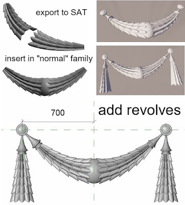
Export to SAT and bring that back into an ordinary GM template. Add a few revolves and it’s looking half decent.  Maybe the tassles are a bit oversized in relation to the central garland.


I need a straight piece hanging down. This was pretty easy. “Save as”, the curved garland and push the middle point into line with the two ends. As discussed above, the panels become very flat. Still don’t understand that but it was simply fixed using the global scale factor “F”.


I intended to open the SAT export in 2014, scale it down a bit, explode and bring back to 2018. (This is partly about applying materials.)  


Sadly some of the panels dropped out on exploding.  So I tried another strategy.

Give the festoon a base plate to sit on, then go to a left side view and rotate the straight garland a bit so the two side rows get buried in the base. Ultimately I should go back and rebuild the massing family, reduce the width of the profiles and number of rows, the re export. But for now this works as a quick fix


Been a while since I fired up Enscape3d. Still working fine, and I fiddled about with Pixlr to come up with the final image.


Already I generated two different curved garlands plus a straight one. Once you have a concept set up in Point World creating variations on a theme is child’s play. Probably need to explore some different curtain panels next. Maybe an attempt at an oak leaf?

In conclusion, recapturing my pumpkin skills could be another way to approach some of those tricky classical motifs. Stay tuned: more to come.


Sunday, March 10, 2019

GETTING IN SHAPE


For the past few weeks I have been recovering from a medical procedure and gradually getting back to my normal routine. That’s one interpretation of the title. Another is that I stumbled across Onshape this weekend, and took my first hesitant steps with this cloud based solid modelling package. I’m using the free version, which means that all my models are in the public domain, but I usually share my work freely anyway so that’s not an issue.


So far I have mostly been using my phone. Works quite well with the s-pen. The desktop version is probably faster (big screen, ribbon menu, right click options) but I like the casual aspect of working on my phone (change of rhythm, work on the move). Nothing spectacular yet in terms of results, but a couple of items that improve on Revit’s native modelling capabilities.


I have a long history of trying to create better geometry for furniture and plumbing families with complex curvature. And in recent years the demands of classical ornament have been a recurrent theme. Onshape has potential in both these areas.


My initial attempts to model scrolls and foliage were useful training exercises that fell short of producing viable Revit families. But I hit paydirt with a spiral, rope motif. Onshape has a built-in helix tool which can be used to generate a sweep. Now it’s possible to generate a spiral with the conceptual massing tools in Revit but it tends to lose it’s shape a bit at the ends and you’re going to have to export to ACIS (SAT) format to get file sizes down.


Onshape also exports to SAT, so that’s the route I’ve been using. Phone to One Drive, open SAT with an older version of Revit, scale and explode, save and reopen in 2018. I generally make families in 2018 now. It’s a compromise between having the latest features and maintaining a minimum of backward compatibility. Exploded SAT becomes freeform or direct shape stuff. Here are some examples of public domain models I downloaded. Surface geometry is going to fail in Revit so results will be patchy.  


You can apply materials, cut with voids, add more Revit geometry.

Getting back to the rope moulding, I ended up with a family that might represent a terracotta tile. A row of these tiles produces a nice traditional linear ornament. I previously developed a system that uses the double nested planting hack to generate repeating linear ornament families that scale parametrically via the height parameter. Sometimes I use railings, but this time I went for line based families.


By the way, I struggled for a while, in Onshape, trying to get the pitch of the spiral to look right before I realised that you need two threads, intertwined.  Just another example of the power of the drawing and modelling processes as aids to active learning. You can look at a shape and think you understand it, but the act of recreating it from scratch is much more demanding and therefore more rewarding.

So flushed with success I decided to tackle the "guilloche" challenge.


This is a motif that has many variations. It’s kind of like a flattened out rope moulding. I guess it’s a play on the whole 2d/3d illusion thing. You can read it as a series of overlapping circles, but like many Islamic patterns, the strap work weaves under and over in a subtle way. I did a Revit version using swept blends but the high point forms a sharp ridge. Onshape gave me a nice smooth loft, based on three profiles. I got a bit carried away with the extra decoration. Often enough you get rosettes placed in the inner circles.


For me, Onshape has a lot of potential, and I appreciate their licencing model. Since I'm using it for personal research, I’m willing to keep everything in the public domain, so I get fully functional software for free and access to all my work on all devices from anywhere with internet.  If you are operating commercially, public domain is not going to cut it, so you’re going to buy a license.  Apart from the secure storage for your work, you’ll get technical support and some extra admin tools.

I know some content creators use Rhino or Inventor to create more complex BIM geometry, but I don’t have access to those tools, so I’m going to give Onshape a try.  Still a lot to learn to achieve a decent level of fluency, but not a bad start.