This is my first attempt at a slightly different format for my posts. The aim is to group the "stuff about buildings" and the "stuff about Revit" into two parts. Readers who don't use the software can skip the second part. Software addicts who don't see the value in my musings of "the way we build" can focus on the "tips and tricks". Hopefully most of you will gain a clearer picture of the synergy between these two aspects of my work. The starting point today is one of Palladio's lesser known Villas.
VILLA GAZOTTI
According to the pictures on the web, this is still a semi-derelict villa. Most of the stucco has fallen off, and there are flowers growing out of the joints in the brick steps leading up to the front porch. It seems that the villa hasn't had the happiest of histories. Palladio was modifying an existing structure for Gazotti who had to sell it on to a Mr Grimani before it was finished in order to solve his cash flow problems. Perhaps he was trying a little too hard to compete with his neighbour whose grand estate dominates the village.

Palladio had two main basic ideas for the central element of his façade: the triple arched porch, and the classical temple portico. This one has the arch motif, but he throws in a pediment for good luck, and an array of 8 pilasters that divide the whole frontage into 7 equal bays. I think it's the only one of his country villas to set up a consistent rhythm right across the full width.

Before I started this exercise, I hadn't really given much thought to the importance of "outdoor rooms" in Palladio's villa plans. This one is a classic front porch, overlooking the street and large enough to lay out a large table on a Sunday afternoon for guests coming from a service at the church next door. There are 3 imposing doorways, leading to the 3 main rooms of the house. It seems to me that these four spaces, (one outdoor and 3 indoors) define the house. The rest is a bunch of much smaller storage spaces and hay lofts stacked up at the back, cramming in 3 floors to the one lofty storey of the master's domain.
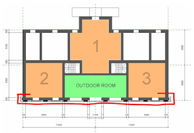
The principal room is cruciform, with an impressive brick groin vault. There is a fascinating photo online of the roof void over these vaults showing the ribbing of the vaults and the massive timber truss and rafters that support the clay tiled roof.

One thing that doesn't come out very clearly from my sheet at present is the contrast between front and rear elevations. From the back it looks pretty much like a storage barn and I am starting to wonder if Palladio's main contribution here was to remodel the façade, basically decorating the shed. The ends of the front wall actually stick out at the sides rather than wrapping around to form a proper side elevation.

Just to recap, what I have built here is a simplified massing model that aims to put Palladio's Villas in context. There is a large square of topography, with subregions for rivers and fields; a few floors and walls, some "lollipop trees, and families to represent buildings.

METHODS USED
Like anything we do using a BIM approach, deciding how much detail to show is critical to success. It's not just a question of imitating reality. We have to consider our goals and develop the model accordingly. Hence the simplified trees. In a similar way, we are always faced with the question "how parametric?" Most of this is directly modelled, much of it judged "by eye". I've bitten off a rather large task here, and can't afford to get too bogged down with accuracy. In any case we don't really know what the Veneto looked like more than 400 years ago at this level of detail. But I am assuming that there were rows of cypress trees, as there are now, and for these I can take advantage of Revit's dynamic array feature, which really comes into its own at masterplanning level. By choosing the "last" option I can nudge around the tree at either end to fine tune both length and alignment of a row. If the density of spacing doesn't look right, just type in a new number. This is parametrics built in to a system tool.

The contextual buildings are loadable families. Inside you have a box (rectangular extrusion) and a nested Roof family which is set up so that the ends can flip between gables or hips. Gables need to be wall colour and hips to be roof colour so you end up with two pairs of parameters: a yes/no and a material for left, then the same again for right.

The switching between hip and gable is achieved by a retractable void extrusion and a simple "IF" formula. If the box is ticked, the extension is set to full depth, which cuts a hip slope. If the box is not ticked the extension is set to zero, and you have a vertical gable. The pitch angle controls the height of the roof via a simple trig formula using the tangent of the angle.

The end result is a family which can be easily switched between 3 conditions: two hips, two gables, one of each. Opinions may well differ on the balance of type and instance parameters for a family like this. In my view there should be a maximum of 4 or 5 types, preferably with simple, intuitive names. Currently I have them set to combinations of roof pitch and material. That way it's easy to select a bunch of and switch types without disturbing the geometry of the layout. It's just a way of introducing variety. Meanwhile, in plan view there are shape handles to make it easy to stretch things around.

So the contextual buildings are simple, variable, highly parametric. By contrast, Palladio's villas are modelled in much more detail but have no built in variability at all. I've tried to gauge the minimum level of detail needed to convey the essentials of each design. The basic room layout is revealed depending on the height of the cut plane, or the clipping of a section box. The principle openings are cut out by voids, and there are simplified mouldings to break up the elevation and reflect Palladio's basic proportions.

It's all done with simple solids and voids, mostly extrusions, a few sweeps, the occasional revolve. But the starting point is a drafting view where I have assembled my source material and scaled it up to ... now there's a question. What size to use ? In a few cases there are dimensions in known units. Then of course there are estimated measurements from Google earth, and finally we have the numbers written on Palladio's own plans. I am quite certain these are Venetian feet (348mm) So I've used a module of 350. External walls are commonly 700mm thick for example, and most rooms are whole multiples.

Then I traced over the source images, creating filled regions for the floor plans so I can copy-paste the sketch into an extrusion in the family.

Elevations are a bunch of detail lines, grouped. A second copy of this group can be swapped out in a clean drafting view and exported to CAD. That's the best method I have for bringing the front elevation into my family. One elevation usually provides enough guidance to create an acceptable massing model.

Maybe you don't see yourself studying the works of Palladio using BIM tools. But why not apply these same methods to an urban design study as part of a concept design report for one of your current projects? Adjacent buildings could be modelled from source material to a similar level of detail as Villa Gazotti here. The more distant cityscape could be assembled from parametric families of various shapes and sizes.
Take the principles. Apply them to your situation.
.
VILLA GAZOTTI
According to the pictures on the web, this is still a semi-derelict villa. Most of the stucco has fallen off, and there are flowers growing out of the joints in the brick steps leading up to the front porch. It seems that the villa hasn't had the happiest of histories. Palladio was modifying an existing structure for Gazotti who had to sell it on to a Mr Grimani before it was finished in order to solve his cash flow problems. Perhaps he was trying a little too hard to compete with his neighbour whose grand estate dominates the village.

Palladio had two main basic ideas for the central element of his façade: the triple arched porch, and the classical temple portico. This one has the arch motif, but he throws in a pediment for good luck, and an array of 8 pilasters that divide the whole frontage into 7 equal bays. I think it's the only one of his country villas to set up a consistent rhythm right across the full width.

Before I started this exercise, I hadn't really given much thought to the importance of "outdoor rooms" in Palladio's villa plans. This one is a classic front porch, overlooking the street and large enough to lay out a large table on a Sunday afternoon for guests coming from a service at the church next door. There are 3 imposing doorways, leading to the 3 main rooms of the house. It seems to me that these four spaces, (one outdoor and 3 indoors) define the house. The rest is a bunch of much smaller storage spaces and hay lofts stacked up at the back, cramming in 3 floors to the one lofty storey of the master's domain.

The principal room is cruciform, with an impressive brick groin vault. There is a fascinating photo online of the roof void over these vaults showing the ribbing of the vaults and the massive timber truss and rafters that support the clay tiled roof.

One thing that doesn't come out very clearly from my sheet at present is the contrast between front and rear elevations. From the back it looks pretty much like a storage barn and I am starting to wonder if Palladio's main contribution here was to remodel the façade, basically decorating the shed. The ends of the front wall actually stick out at the sides rather than wrapping around to form a proper side elevation.

Just to recap, what I have built here is a simplified massing model that aims to put Palladio's Villas in context. There is a large square of topography, with subregions for rivers and fields; a few floors and walls, some "lollipop trees, and families to represent buildings.

METHODS USED
Like anything we do using a BIM approach, deciding how much detail to show is critical to success. It's not just a question of imitating reality. We have to consider our goals and develop the model accordingly. Hence the simplified trees. In a similar way, we are always faced with the question "how parametric?" Most of this is directly modelled, much of it judged "by eye". I've bitten off a rather large task here, and can't afford to get too bogged down with accuracy. In any case we don't really know what the Veneto looked like more than 400 years ago at this level of detail. But I am assuming that there were rows of cypress trees, as there are now, and for these I can take advantage of Revit's dynamic array feature, which really comes into its own at masterplanning level. By choosing the "last" option I can nudge around the tree at either end to fine tune both length and alignment of a row. If the density of spacing doesn't look right, just type in a new number. This is parametrics built in to a system tool.

The contextual buildings are loadable families. Inside you have a box (rectangular extrusion) and a nested Roof family which is set up so that the ends can flip between gables or hips. Gables need to be wall colour and hips to be roof colour so you end up with two pairs of parameters: a yes/no and a material for left, then the same again for right.

The switching between hip and gable is achieved by a retractable void extrusion and a simple "IF" formula. If the box is ticked, the extension is set to full depth, which cuts a hip slope. If the box is not ticked the extension is set to zero, and you have a vertical gable. The pitch angle controls the height of the roof via a simple trig formula using the tangent of the angle.

The end result is a family which can be easily switched between 3 conditions: two hips, two gables, one of each. Opinions may well differ on the balance of type and instance parameters for a family like this. In my view there should be a maximum of 4 or 5 types, preferably with simple, intuitive names. Currently I have them set to combinations of roof pitch and material. That way it's easy to select a bunch of and switch types without disturbing the geometry of the layout. It's just a way of introducing variety. Meanwhile, in plan view there are shape handles to make it easy to stretch things around.

So the contextual buildings are simple, variable, highly parametric. By contrast, Palladio's villas are modelled in much more detail but have no built in variability at all. I've tried to gauge the minimum level of detail needed to convey the essentials of each design. The basic room layout is revealed depending on the height of the cut plane, or the clipping of a section box. The principle openings are cut out by voids, and there are simplified mouldings to break up the elevation and reflect Palladio's basic proportions.

It's all done with simple solids and voids, mostly extrusions, a few sweeps, the occasional revolve. But the starting point is a drafting view where I have assembled my source material and scaled it up to ... now there's a question. What size to use ? In a few cases there are dimensions in known units. Then of course there are estimated measurements from Google earth, and finally we have the numbers written on Palladio's own plans. I am quite certain these are Venetian feet (348mm) So I've used a module of 350. External walls are commonly 700mm thick for example, and most rooms are whole multiples.

Then I traced over the source images, creating filled regions for the floor plans so I can copy-paste the sketch into an extrusion in the family.

Elevations are a bunch of detail lines, grouped. A second copy of this group can be swapped out in a clean drafting view and exported to CAD. That's the best method I have for bringing the front elevation into my family. One elevation usually provides enough guidance to create an acceptable massing model.

Maybe you don't see yourself studying the works of Palladio using BIM tools. But why not apply these same methods to an urban design study as part of a concept design report for one of your current projects? Adjacent buildings could be modelled from source material to a similar level of detail as Villa Gazotti here. The more distant cityscape could be assembled from parametric families of various shapes and sizes.
Take the principles. Apply them to your situation.
.