I have a weekly training session at GAJ called "Intermediate Family Editor". It is aimed at people who have been using Revit actively on projects for a year or two but haven't got too far with the family editor. This post is a revision aid for that class. It's fairly basic stuff, but some of you may find it useful.
We are going to make some wall-based families. New family: Metric Generic Model wall based. This opens in plan view.

Note the 3 ref planes: "Centre Left-Right", "Wall" (on the centre line of the wall) & "Back" which is locked to the face of the wall with a zero dimension. I'm not really sure why it is called "Back" since it is locked to the "Placement Side" of the wall, which many would consider to be the "front". Perhaps the idea is that this refers to the back of the object which we are going to place on the wall. But what if that object is going to be a void which cuts into the wall? Let's move on.
Note also the text object used to label the Placement Side. This is just a dumb text object. You can edit this or move it to the other side of the wall and it won't have any effect on the elevation view called "Placement Side"

So let's go to that view and draw some more reference planes. Two of them are parallel to the centre F/B and equalised with a constrained dimension. The third is parallel to the ground. Add dimensions and label them as Width & Height. Make these instance parameters.

We're going to make some geometry now, and we want to lock it to the ref plans and the level. We don't want to lock it to the wall by mistake. We could hide the wall using the sunglasses. Instead we will simply pull the base of the wall down a little way so that we can see the Reference Level clearly. Next set the work plane to "Back". On the "Create" tab, select "Extrusion".

Choose the rectangle tool. Pick 2 corners. Lock the 4 padlocks that appear. Finish extrusion. Note that the extrusion projects backwards through the wall. I don't understand why this is. Could it be a mistake in the way the template was originally set up ? Not to worry. Go to plan view and draw a reference plane.

Place a dimension between this new plane and "Back". Make sure you are picking the ref plane, not the face of the wall. Label the dimension with a new type parameter called "Depth". Select the extrusion, and use the shape handles to drag it inside out. Snap on to the new ref plane and lock the padlock.

That's basically it for our first family, but we need to test it. Select the wall and rename the type as "150" That's the thickness of the wall as it comes out of the box (Metric Template) Duplicate to make a new type. Call this "250" and edit the wall structure to make its thickness 250mm. Now that we have two wall types, we can swap between them to check that the family will behave properly on walls of different thickness.

Before using a family in a project, it is good practice to "flex" it. Basically you need to vary each parameter, one be one to check that it is behaving as expected.

Start a new project. Create a wall. Go back to family editor, "Load into Project" Place several instances. Set up two types with different depths. Experiment with the instance values for width & height.

In the project browser, find the family, and rename it. At GAJ we use 2 digit codes in our naming conventions. 38 refers to "wall features" ... could be panels like this one, recesses, niches, decorative plaques ...

Now we can go back to family editor & make a new version. When we load it back into the project it will be recognised as a different family because we gave the original version a new name. Add 4 new reference planes. Create dimensions and label them as "Border Width" (Type Parameter)
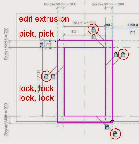
Edit extrusion. Draw rectangle. Pick the 2 outer corners. Lock the 4 padlocks.

Load this new version into the project and place a few instances. Once again, create 2 types and experiment with the instance parameters for width & height. Choose one instance of each type, and set the elevation to zero.

Notice that despite the different border width of the 2 types, Revit interprets the lowest point of the extrusion as the origin of the family in both cases. This may be what you want. Alternatively, you may want to have a consistent origin point, let's say the reference level. Here's how.

Back in family editor, draw a ref plane that coincides with the ref level and lock the padlock. Select this plane and check the "Defines Origin" box. Load into project.
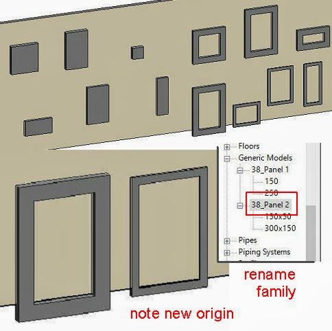
Note the now origin location. By the way, we didn't need to do this with the first version of the family because there was no geometry projecting below the Reference Level. So let's move on to the third version of the family. Don't forget to rename version 2 first.

New family. "Metric Profile". Add four ref planes below the default horizontal plane. Constrain them with an equalized dimension string. Add and overall dimension and label it "W". Create a vertical ref plane to the right of the existing plane. Add a dimension and label it "T"
Now use a formula to make "T" change in proportion to "W" (T = W/10)

On the "Create" tab, choose "Line". Uncheck "Chain" and start to draw lines. We unlocked the chain function so that we can lock each line as we draw it. Draw 4 lines, locking them as you go. Close the loop with a semi-circle. Choose the "Start-End-Radius Arc". Pick the two end points and feel it snap to a semi-circle. Flex the family to check that it resizes proportionally as you vary "W" Load the profile

Delete surplus reference planes (the 4 outer planes) and parameters (Depth) On the "Create" tab, choose "Sweep". "Sketch Path". Pick opposite corners. Lock the 4 padlocks, finish path.

select profile. Choose the family you have just loaded. Note the rotation. We want it to lie flat against the wall face. In this case it can be achieved by selecting a rotation angle of -90. Finish the sweep.

The last step involves linking parameters. We will use the small "associate family Parameter" button that resides at the end of the line for each parameter. Find the profile in the project browser. Edit properties. Click on the button for the "W" parameter. Associate it with "Border Width". The "Border Width" parameter will now act as expected, but instead of controlling an extrusion directly, we are controlling a sweep via the nested profile family.

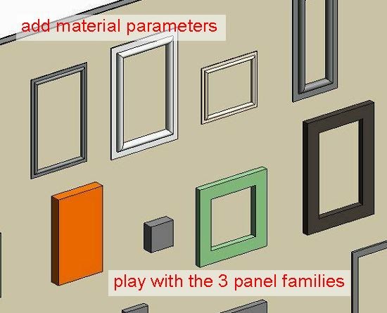
Load into project. Place a few instances. Create types and flex the instance parameters. You can go also back to each family and add a material parameter.
So we have created 3 wall-based panel families. These are projecting panels, but we could just as well have created voids that cut into the wall surface. You can probably think of all kinds of variations on this type of family. They could represent plaster mouldings, grc components, notice boards, wall-fixed mirrors with moulded frames. I hope some of you will find this useful.
We are going to make some wall-based families. New family: Metric Generic Model wall based. This opens in plan view.
Note the 3 ref planes: "Centre Left-Right", "Wall" (on the centre line of the wall) & "Back" which is locked to the face of the wall with a zero dimension. I'm not really sure why it is called "Back" since it is locked to the "Placement Side" of the wall, which many would consider to be the "front". Perhaps the idea is that this refers to the back of the object which we are going to place on the wall. But what if that object is going to be a void which cuts into the wall? Let's move on.
Note also the text object used to label the Placement Side. This is just a dumb text object. You can edit this or move it to the other side of the wall and it won't have any effect on the elevation view called "Placement Side"
So let's go to that view and draw some more reference planes. Two of them are parallel to the centre F/B and equalised with a constrained dimension. The third is parallel to the ground. Add dimensions and label them as Width & Height. Make these instance parameters.
We're going to make some geometry now, and we want to lock it to the ref plans and the level. We don't want to lock it to the wall by mistake. We could hide the wall using the sunglasses. Instead we will simply pull the base of the wall down a little way so that we can see the Reference Level clearly. Next set the work plane to "Back". On the "Create" tab, select "Extrusion".
Choose the rectangle tool. Pick 2 corners. Lock the 4 padlocks that appear. Finish extrusion. Note that the extrusion projects backwards through the wall. I don't understand why this is. Could it be a mistake in the way the template was originally set up ? Not to worry. Go to plan view and draw a reference plane.
Place a dimension between this new plane and "Back". Make sure you are picking the ref plane, not the face of the wall. Label the dimension with a new type parameter called "Depth". Select the extrusion, and use the shape handles to drag it inside out. Snap on to the new ref plane and lock the padlock.
That's basically it for our first family, but we need to test it. Select the wall and rename the type as "150" That's the thickness of the wall as it comes out of the box (Metric Template) Duplicate to make a new type. Call this "250" and edit the wall structure to make its thickness 250mm. Now that we have two wall types, we can swap between them to check that the family will behave properly on walls of different thickness.
Before using a family in a project, it is good practice to "flex" it. Basically you need to vary each parameter, one be one to check that it is behaving as expected.
Start a new project. Create a wall. Go back to family editor, "Load into Project" Place several instances. Set up two types with different depths. Experiment with the instance values for width & height.
In the project browser, find the family, and rename it. At GAJ we use 2 digit codes in our naming conventions. 38 refers to "wall features" ... could be panels like this one, recesses, niches, decorative plaques ...
Now we can go back to family editor & make a new version. When we load it back into the project it will be recognised as a different family because we gave the original version a new name. Add 4 new reference planes. Create dimensions and label them as "Border Width" (Type Parameter)
Edit extrusion. Draw rectangle. Pick the 2 outer corners. Lock the 4 padlocks.
Load this new version into the project and place a few instances. Once again, create 2 types and experiment with the instance parameters for width & height. Choose one instance of each type, and set the elevation to zero.
Notice that despite the different border width of the 2 types, Revit interprets the lowest point of the extrusion as the origin of the family in both cases. This may be what you want. Alternatively, you may want to have a consistent origin point, let's say the reference level. Here's how.
Back in family editor, draw a ref plane that coincides with the ref level and lock the padlock. Select this plane and check the "Defines Origin" box. Load into project.
Note the now origin location. By the way, we didn't need to do this with the first version of the family because there was no geometry projecting below the Reference Level. So let's move on to the third version of the family. Don't forget to rename version 2 first.
New family. "Metric Profile". Add four ref planes below the default horizontal plane. Constrain them with an equalized dimension string. Add and overall dimension and label it "W". Create a vertical ref plane to the right of the existing plane. Add a dimension and label it "T"
Now use a formula to make "T" change in proportion to "W" (T = W/10)
On the "Create" tab, choose "Line". Uncheck "Chain" and start to draw lines. We unlocked the chain function so that we can lock each line as we draw it. Draw 4 lines, locking them as you go. Close the loop with a semi-circle. Choose the "Start-End-Radius Arc". Pick the two end points and feel it snap to a semi-circle. Flex the family to check that it resizes proportionally as you vary "W" Load the profile
Delete surplus reference planes (the 4 outer planes) and parameters (Depth) On the "Create" tab, choose "Sweep". "Sketch Path". Pick opposite corners. Lock the 4 padlocks, finish path.
select profile. Choose the family you have just loaded. Note the rotation. We want it to lie flat against the wall face. In this case it can be achieved by selecting a rotation angle of -90. Finish the sweep.
The last step involves linking parameters. We will use the small "associate family Parameter" button that resides at the end of the line for each parameter. Find the profile in the project browser. Edit properties. Click on the button for the "W" parameter. Associate it with "Border Width". The "Border Width" parameter will now act as expected, but instead of controlling an extrusion directly, we are controlling a sweep via the nested profile family.
Load into project. Place a few instances. Create types and flex the instance parameters. You can go also back to each family and add a material parameter.
So we have created 3 wall-based panel families. These are projecting panels, but we could just as well have created voids that cut into the wall surface. You can probably think of all kinds of variations on this type of family. They could represent plaster mouldings, grc components, notice boards, wall-fixed mirrors with moulded frames. I hope some of you will find this useful.


