Wednesday, September 30, 2015

JOHN SOANE WAS HERE

As I was preparing the latest model for upload the other day, I decided to locate it in the City of London.  I'm talking about the Location tool on the Manage tab in Revit.  It takes you to a mapping service where you can drag a map pin from Revit HQ in Boston Mass to somewhere else on the globe.  Not sure if everyone gets the same service, but I noticed mine was Bing Maps.  I rather like the axo projection this brings up when you zoom in. 

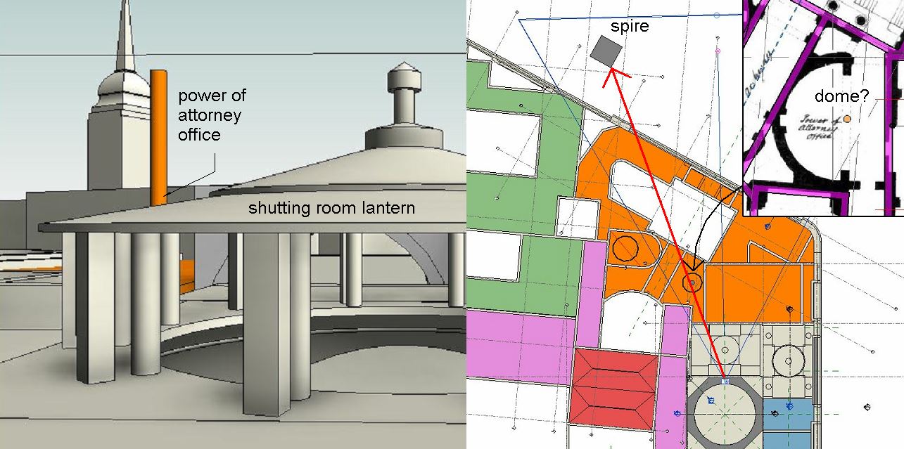
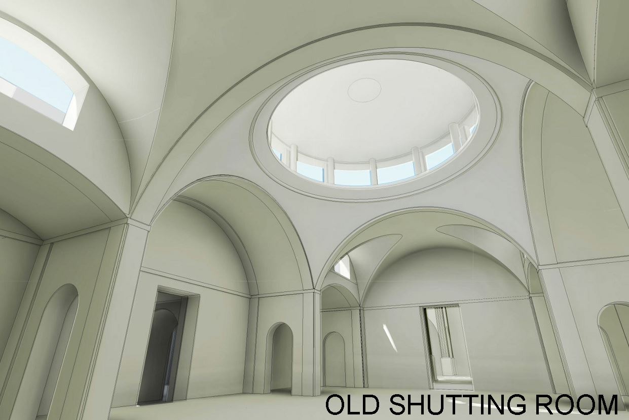
What surprised me a bit was the octagonal lanterns and barrel vaults in the South East corner ... almost like Soane's treatment of the last two banking halls he built.  But looking closely it's not quite the same.  This is Herbert Baker paraphrasing Soane.  The proportions and alignments are not quite the same.


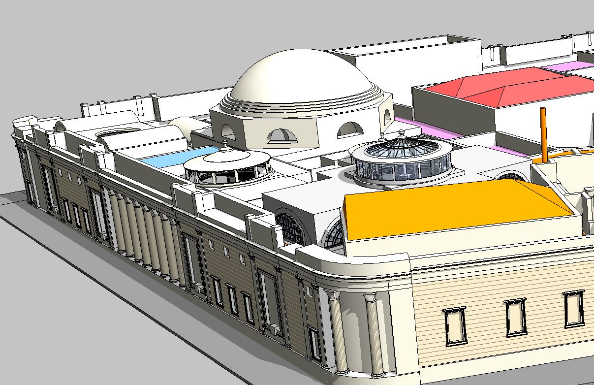
Having set the location I might as well do a solar study.  You can check this out on A360.  Drag the sun around and see the shadows move, reading off the time and date as you go.  Lots of circles in there (rotunda, 5 lanterns, compass directions, the sun of course ... and why not throw in the old Bank logo too ... bit odd the way the spear point slices England in two ... what do you think Ian ?)


When you think of it, Soane's bank was kind of like a Medieval Town: organised chaos within a perimiter wall.  And when you look at Soane's drawings it's obvious that the screen wall was built like that ... even had a walkway going around that the night watch could patrol.  Apparently they had a room full of pikes for these guys to carry, "just in case". 


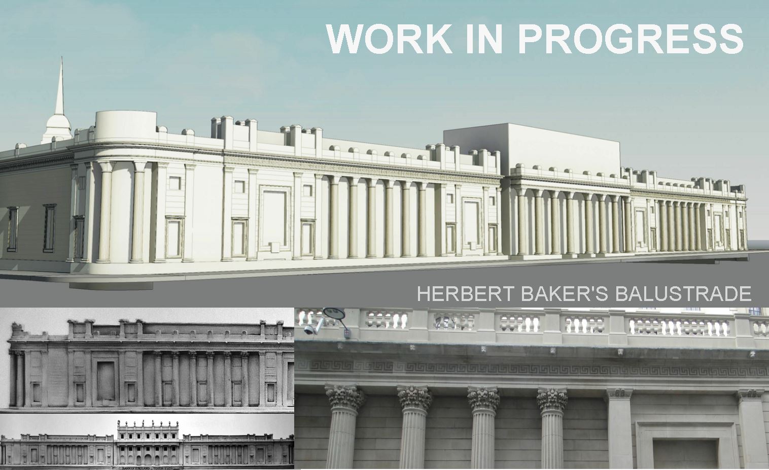
Looking at these drawings brought me back to the parapet ornaments that I am hoping someone will model.  I wanted a better image to stir the troops into action and it struck me that maybe I had seen them in one of his other buildings that I photographed a few weeks ago.  And yes, there are a couple of variations on that theme in the Dulwich Picture Gallery, apart from the phone box at the back.


His church opposite Gt Portland Street underground has rather a fun variant with pineapples on sticks coming out the top.  Better not say too much about those in case I slip on a Freudian banana skin.


So moving on to his other churches and guess what ... more variations on the same theme.  This is starting to remind me of the planters in Frank Lloyd Wright's Chicago projects that I studied a year ago.  Interesting how architects get fixated on a favourite little detail and worry it to death over the years.


Speaking of death, there it is again on the tomb that he shared with his wife and eldest son.  Tragic that he saw them both buried there long before his turn came around.  Quite a few interesting variations here if you look carefully.  Wouldn't it be fun if someone made a series of parametric families to capture these different interpretations of a round-headed ... what is it anyway?  Bit like an acroterion, but not quite.


And of course there are his two homes, town and country, both of these had to have them.  I think the ones dotted all over the frontage of the Museum are pretty close to what he used on the Bank actually.  Take that as your model.


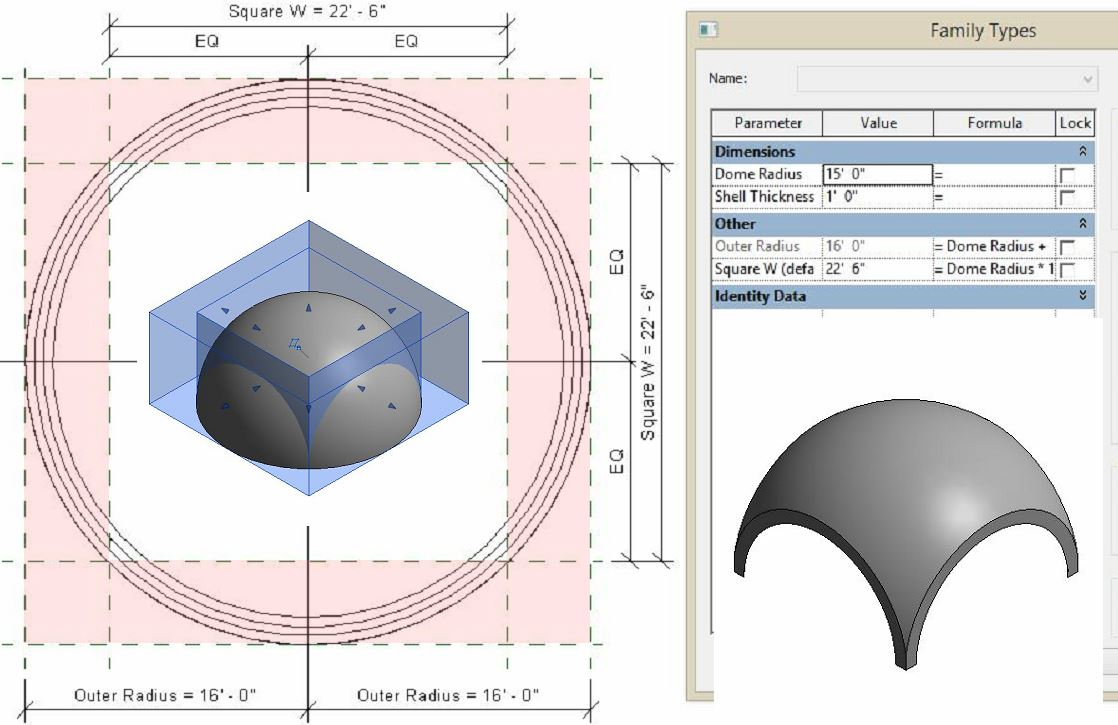
So we are back to Threadneedle Street (the old lady) and a little collage from the hugely impressive archive of drawings that Sir John left behind for us.  Maybe it would be nice to get this "whatever it is" 3d printed, sell them as "John Soane Paperweights"  Would have to scale them down a bit of course, the originals are 2' 1" square (cubed perhaps)


And finally I have to give a shout out to Sheikh Uduman, a member of our local BIM User Group who has stuck his hand up and contributed 3 families in response to my appeal.  See how easy it is ?  Why not throw something into the pot ?


So that's it, lumps of stone that our hero left around all over the place, as if to say "John Soane was Here !"

Sunday, September 27, 2015

ASK NOT WHAT PROJECT SOANE CAN DO FOR YOU

This post is directed at all those who have registered for Project Soane but not yet contributed anything (except maybe a like or two).  Perhaps you are having trouble deciding what to make.  Maybe you feel intimidated by some of the "advanced" contributions that have been uploaded so far.  You shouldn't be.  This is "crowd sourcing".  It means we need a whole bunch of people to get actively involved. 

My goal is to suggest a number of relatively small, self-contained tasks suitable for an "average" Revit user, which would also be valuable contributions to the project.  I am hoping that I will then be able to incorporate these elements into the larger assemblies that I have started to rough out.


For example over the weekend I spent some time improving the external screen wall that I had mapped out in outline 3 or 4 weeks ago.  There are a number of decorative elements that need to be made as families, such as the urn that features at Tivoli Corner.  4 feet high, one revolve & one extrusion.  Maybe include a material parameter. 

Download the image below, bring it into family editor, scale it up & trace over. Upload the results to Project Soane.  Half an hour max.


There are other elements that have already been made, but at present are very crudely represented using placeholder families.  It would be great if a few of you would volunteer to create versions of these at a higher level of detail.  Doesn't have to be perfect, just a little bit better than what we have at present.  Baby steps will get us there if everyone pitches in.  For example there are  two entrance gateways along Lothbury.


Three families here that need work, ranging from very simple to intermediate.  There is a parapet element that is used repeatedly, right around the building.  It may be two curves, crossing to form a kind of groin vault, or it may be more like one of Soane's canopy domes.  It was drawn both ways and maybe both types were used.  Old photos aren't a sure guide either because the parapet was raised some time after Soane's departure.  I think we should make both versions.


If you have a little more time to spare, there are parapet elements based on scrolls and shells.  There is a variant on this that wraps around the curved corners also. 


Then there are the gates and doors: at least one in each of the 4 elevations.  Along Lothbury we have two, almost identical gateways: the bullion entrance and what amounts to a tradesmen's entrance.  Sometimes these are shown as solid doors, sometimes as wrought iron gates.  The bullion entrance has both an inner and an outer gate.  Perhaps we should show the outer on as solid, and the inner as wrought iron.


Another very simple one is the key pattern that runs around as a frieze on the entablature along Threadneedle Street & Bartholomew Way.  I have estimated the size and drafted out the geometry of the basic repeating module as shown in the next pic.  Two extrusions, one half the thickness of the other will do the trick here.


I have dropped a simplified placeholder in place at present.  I made it as a generic model family then nested this into a baluster.  Then I defined a railing type with these balusters spaced appropriately.  You can now draw straight and curved runs of the pattern with consummate ease.  In the model I used the "pick" option to draw the path and selected the flat face of the wall sweep that we want to host the frieze.  That worked fine.  You can still adjust the endpoints of the path to get the pattern to start and stop where you want it.


There are lots more elements that need family development.  Different parapet treatments on the Princes Street facade for example.  Just open up the model from Project Soane and take a look.  Lots of stuff in there that needs work. 


In case you are wondering where some of these reference images are coming from, I downloaded them from the Soane Museum Online Archive.  There are links in the Project Soane Wikipages that take you there.  Literally hundreds of drawings for the bank are available here.  They are not quite as high res as the ones provided in the data folders, and take care because many of them are early studies, not the final design.  That said, it's a fantastic resource.


I am totally hooked on this mission at present, but unfortunately also very busy at work.  (I shouldn't complain, it pays the bills :)  So I don't have time to model all this stuff and my major focus is on trying to tie everything together, resolve dimensional issues and fine tune alignments.  Why not lend a hand ?

A couple of people have made really major contributions in terms of modelling some of the internal spaces.  But if you don't feel you have the time or the skills to tackle something that big, there are many, many smaller elements which you could contribute to the project.  I hope these suggestions will help.


So that's where I am with the exterior.  By the time you read this I should have uploaded the latest version.  I like this image because it reminds me of an architectural model.  Soane was a great one for making architectural models of his proposals (see bottom left)  Also note that the current balustrade details are very different from Soane's version.  Herbert Baker lopped all that off and just ran a simple balustrade around. 

Perhaps that makes sense in terms of easing the transition to the giant wedding cake he was asked to place within the perimeter, but Soane's treatment has much more charm, don't you think ?

Thursday, September 24, 2015

UP ON THE ROOF WITH MR SOANE

This is a bit of detective work that I did while modelling the lanterns of Soane's banking halls at the Bank of England.  There is an old photo that claims to be the lantern to the Old Shutting Room and I thought it might be interesting to recreate it with a camera shot in Revit.


I was interested to know what the other lantern was, behind and to the left.  The church spire is clearly St Margaret Lothbury, which I photographed on my recent visit.  One of Wren's many City churches I believe. 


I tried to line this up with a candidate space for a dome/lantern, but the nearest fit I could find is the Power of Attorney Office, represented here by an orange pole.  The problem is that this is a semi-circular space.  Doesn't look right to me.


Even worse, when I slotted in Russell's CTO as a link, its lantern popped up into view to the right.  Definitely not matching the photograph.


So then I followed a hunch and took a shot from behind the Stock Office, looking past the CTO towards the spire.  Near perfect match.  What is more if you peer through the dirty glass in the photo you can see the arched window of the CTO, and even more telling, the steel brackets of the Stock Office lantern. That's clear enough for me.  Wrongly labelled photograph, it happens.


If I am right then we have a photo of the exterior of the CTO lantern.  From the interior shot of the same age this appears to be glazed.  Is that dirty glass that we can see?  I think it must be.  The Stock Office on the other hand is clearly covered in sheet metal.  And we know that it had a plastered ceiling, from the photographs and from the reconstructed version.

 
By the way, the pitched roof in the background is the Consols Library, which is the orange roof in the foreground of the next picture.
 

This really is a fascinating roofscape.  I definitely haven't unlocked  all its secrets yet, but the pieces are starting to fall into place and it's much more interesting than I had imagined.  You can see why he was keen to impose order to the whole complex with his exterior screen wall.  It really is quite a hodge-podge, and I haven't even started adding the chimneys which you can see in the photograph and deduce from the many fireplaces in the drawings and interior shots.  Of course they had coal fires, all the buildings did, hence the famous London Smog.

I'll leave you with this thought.  The Bank of England is starting to remind me of a box of toys.  When my kids were young we had these large drawers on wheels that went under their beds.  Just gather all the toys up from the floor and wheel them away for the night.  Soane created this cool, suave, exterior screen, a neat and tidy box to contain the chaotic collection of toys that the bank had generated to house its activities over a century or so of piecemeal growth. 

Weekend beckons, let's see what I can come up with :)
 

Sunday, September 20, 2015

JOHN SOANE & CANOPY DOMES

There's a half-finished post about my work on Project Soane from a couple of weeks ago that I may come back to, but for now let me skip ahead to what I've been working on this weekend.

I've been getting to grips with the interior layout of the Bank of England.  Just broad brush stuff: what was there when Soane was first appointed and how he renovated and expanded it over a period of 40 years or so. 


Then I started to home in on the series of banking halls around the Rotunda that he renovated in two major phases.  This work is partly informed by some old photos taken by Frank Yerbury shortly before most of the bank was demolished to make way for the current version.  These were on a DVD that I bought at the Bank Museum in early August.  Some of these spaces go by different names based on evolving usage.  I am using the names on these old photos which I find relatively easy to remember.


The photos are very useful because the drawings from Soane's office show the design in development and sometimes present conflicting information. I have been exploring this series of spaces as variations on a common theme.  All of them have central domes buttressed by 4 vaulted bays and 4 smaller spaces in the corners.  Like Soane I started with the Stock Office, which has been renovated to house the current museum. This was fitted into an existing rectangular space to replace a dilapidated existing hall.  He chose masonry vaults and domes to avoid the problems associated with the previous timber roof structures.


These halls were built, one by one, within existing shells, so I decided to model them first as Generic Model families: simple, quick massing studies to act as a guide to later work.  I wanted to resolve the major issues of scale and alignment before investing too much effort in detail. There are connections between the rooms that need to be lined up and interesting relationships between the various roof levels as they fit together like a jigsaw puzzle with interlocking light wells


I haven't done pendentives before in Revit.  Turns out they are quite straightforward.  Basically we are looking at a device for making the transition from square to circle: taking a dome and bringing it down onto 4 supporting columns.  There always has to be buttressing to deal with the lateral thrust, but the main wait is coming down on the corner columns.  It's clear from the drawings that the roofs are flat, so I made my pendentives from a box cut by a revolve.


In Soane's domes the centre of the dome is often well below the springing point leading to his characteristic shallow arches meeting the columns at an angle. That's how the Stock Office works.


But sometimes he has sufficient height to allow a full semicircle with the dome flowing down smoothly into the columns.  The colonial office is a good example.


So let's take a closer look at pendentive geometry.  I made a basic parametric family to illustrate this.  We start off with a revolve that creates a hemispherical shell.  Parameters for inside radius and shell thickness. Formula to add these together for the outer radius.


Now set up a reference planes to define a square.  We're going to use these to control a void in the form of a square donut.  This will cut away the sides of the dome creating 4 arches and 4 point supports.


To complete the picture we need upper and lower cutting planes that can also be varied parametrically.  I've set this whole thing up so that the cutting planes are controlled as fractions of the dome radius.  That way, when you type in a new radius the whole thing scales up while maintaining its basic shape.


The end result is a family with 5 instance parameters that can change its size, an vary between a full hemisphere and one of Soane's relatively flat "canopy domes".  So much for basic dome theory.
A set of pendentives can be used to support a simple dome, or a dome on a drum, or lightweight lantern which is what we see at the Bank of England. In the stock office he uses decorative steel brackets to support the lantern roof, shallow arches at the sides, and groin vaults at the ends which allow for steel framed clerestory windows above the corner bays.  These corner bay receive additional daylight from circular holes cut through the ceiling.


To the left you can see a doorway that leads through to the Old Shutting Room which was the next space that Soane rebuilt, once again fitted within and existing shell of perimeter walls.  You can see from the way that Soane places 4 columns around each of the corner bays that he is not relying on these older walls to carry any load.  Everything can be taken down to new foundations within the interior.


The same strategy is used in the Shutting Room.  The door in front of us is the one we saw before coming from the Stock Office, while the one on the left leads to the Consols Transfer Office which is part of the extensive North-East extension that Soane built over the next few years.  This has already been modelled in some detail by Russell Fuller Hill, an excellent contribution which helped me to build a simpler massing model.


You can see my take on the CTO on the left in orange.  This is again a Generic Model Family, but nested within a link so it can be easily swapped out with Russell's version.  That's the strategy I'm aiming towards here, a series of modules with different versions that can be loaded and unloaded depending on where your focus is and the processing power that you have available.


I haven't gone into as much detail as Russel.  No need to duplicate his efforts, but by standing on his shoulders and with the benefit of the old photographs I think I have been able to progress our understanding of what was actually built.  For example the arches that connect the side bays to the corner spaces are lower in my version.  Russel had followed the majority of the drawings, but the photos suggest that Soane made a late change and one drawing (which I think is a record of progress on site) seems to confirm this.


The photos suggest that the design for the casing to the columns was also changed, simplified down to a single recess with a Greek key moulding for the capital.  These are all subtle changes, but show an ever thoughtful architect reflecting on his design and making late adjustments.  The lower arch in particular has practical implications in that it keeps the crown below the springing point of the arches to the corner bays so that these can have a simple arched ceiling rather than the groin vault originally envisaged.


With some reluctance I have rotated the Consols Transfer Office and the Shutting Room by 1 degree.  This is to line up an axis from the rotunda, through these two spaces to the apse at the end of Lothbury Court.  This also brings the CTO closer into line with Cockerell's plan which we have chosen as our common base and from which I developed my guide grid.  For the moment I end up with double walls with wedge shaped cavities in some locations. 


I think it's important to make the connections between the rooms fall in more or less the right places, and to maintain the most obvious axial alignments.  I am intrigued by this aspect of Soane's work: how he adapted to the difficult angles he inherited and created spaces that may look slightly awkward in plan, but would have flowed quite naturally and regularly as a walked experience.

It also strikes me that the CTO does not have full columns up against the perimeter walls, like the previous two banking halls.  This suggests that the walls themselves are loadbearing, which is logical enough given that this is a completely new extension.  These are the kinds of insights that I believe justify the use of BIM on a historical research project of this nature.  Revit makes you think like a builder.


And as an ex-bricklayer, I do hope I can find time to model the construction of part of one of the roofs over these vaults and pendentives.  The drawings show "crop walls" which I would have called "dwarf walls" and spanning over them "York Paving" slabs, which is basically the same material that I saw used for the floors in the reconstructed Stock Office.

 Was that the final finish?  What about waterproofing ?  A roofscape photo shows sheet metal on a portion of flat roof around the lantern, but this could have been added later. 


Oh and the three black holes at the end of the CTO in the drawing ?  I'm quite sure these are skylights in the ceiling of the passage leading towards the Consols Library, which is directly behind the exterior screen wall and therefore has no windows.  It was accessed via half a dozen steps at the end of the CTO. 


They would have been very similar to the ones in the Stock Office, probably covered with a small octagonal lantern like the one you can see in this photo that I took from inside the museum.  It's a bit washed out, but clearly visible.