Showing posts with label Notre Dame. Show all posts

Sunday, August 9, 2020

KIDOLOGY

A couple of weeks ago The Revit Kid (aka Jeff Pinheiro) got in touch and asked me to appear on his podcast “BIM after dark” to showcase the Notre Dame model.  The podcast took place on Thursday night.

https://www.youtube.com/watch?v=QqJZKKhoVHs&feature=youtu.be


I probably should practice looking at the screen while I think.  Seems like my eyes skew “up and away” when I’m thinking 😊.  Also note the face masks and the Zimbabwe flag decorating the back wall of my apartment.


In preparation for this session I put some time into annotating and organizing the sheet set to tell a story.  The grid studies sheet was already there.  I just added some explanatory text.  How many weekends did I sped puzzling through the reference material, comparing measurements and deciding whether to adjust the model to a new grid?  It went through at least 3 iterations, if I remember right, but we now have something that reflects the size of each bay quite closely, and maintains the basic relationships, but keeps the setting out orthogonal.

This sheet serves as a record of how that works.


Alfredo made a very nice cutaway “view” for his AU session last year, and I have updated this with a few annotations.  It serves well as an introductory sheet.  It was created by placing three views on a sheet and carefully adjusting their section boxes.  You have to place the views in the right order to get them to “overlap” convincingly.  “Send to back” only works with 2d elements.


The upper floor plan.  I love the way this sheet has turned out.  It has developed slowly over the months.  The elevations were added to set up “tasks” based on starter families.  The windows were tagged with their family names, and those families placed in a series of folders along with reference images.  Francois has risen to the challenge of developing these elements, and made excellent progress, though not yet complete. So the windows are now tagged with codes (Type Mark) which refer back to a window types sheet (Legend)

While preparing for this talk, I added some notes and photos so that this sheet now gives a splendid overview of the Tribune Galleries, and of the strengthening works around the crossing by VLD.  I puzzled over the reason for those non-standard bays, from the time we first started the model.  At one time I had decided it was a device to disguise the much wider bay between grids 8 & 9.  The full sequence of events and structural logic has only dawned on me in the past couple of weeks. 


At this point, I took my first detour into family editor.  These small flights of steps occur in two places at the ends of the Tribune Galleries.  In a way they are like a straightened out spiral stair.  But they are also precursors of the “cantilever stair” which became so common in the domestic architecture of Europe from Renaissance times until quite recently.  More accurately called a “torsion stair” each stone tread is supported on 3 of its corners: two embedded in the wall, and the third resting on the step below.

I do love making items like this in Family Editor.  Nothing fancy, just extrusions and a couple of parameters … one level of nesting.  But it’s a wonderful way to understand something that catches my eye in the work of builders past.


I’m rather proud of the next sheet, which combines a large central perspective view with smaller plans and sections, plus a couple of small internal camera shots.  This serves to illustrate some complex spatial relationships relating to an enlargement of the clerestory windows that was undertaken almost as soon as the original design was complete.  The story is further complicated by changes that were made by Viollet-le-Duc in the nineteenth century: strengthening the crossing to take the weight of his new spire.

For me, this sheet exemplifies the discovery process that takes place on a collaborative historical investigation like Project Notre Dame.  Week-by-week we gradually tease out a story that spans several centuries of human experience.


Segue to the vaults sheet, by noting those vaults on the previous sheet that are higher on the outside face.  This is a feature of ribbed gothic vaults that I had not been aware of before modelling Notre Dame.  Now, of course, I see it everywhere when I visit old cathedrals.  Alfredo took the adaptive route (what I call “Point World”) and I took a quick look at his 8-point vault, used in the Bell towers.  By way of contrast, I then opened up my attempt to use the traditional family editor to create a flexible 4-part vault with the ability to cover rectangular bays of different sizes, and to selectively lift the outer arches on any of the four sides. 

There are pros and cons to both approaches of course, and I think there is still room for improvement in the way we are representing the vaults.  That applies to most aspects of the model actually.


Jeff passed on a couple of questions from the chat, but I didn’t get to read through the comments till next day.  Interesting feedback. 

On the right you can see drawings by VLD explaining a method for constructing the vault infill between the arched ribs.  Fascinating to me as a former bricklayer.


I decided to add jpegs to the elevation sheets. In the process I noticed, for the first time, that we have two old photos taken from a similar angle, one just before VLD restored the spire, and one shortly after.  Looking closely at these, the changes he made to the windows around the crossing are very clear, also the addition of clock faces, and the small stone pyramids capping the spiral stairs.


West End Story … a study sheet for the West End with its Bell Towers and King’s Gallery.  The levels are quite tricky … some tweaking of View Range parameters required.  Assembly of this sheet was the final stage in a long process of understanding how these various spaces fit together; the galleries, balconies and passages that link them together.

Last of the Family Editor detours, featuring the double-nested planting hack and imported mesh geometry with hidden edges.


Alfredo had started to set up a sheet for the Rose windows. I adjusted the scales and added a strip on the right-hand edge.  Legend views of Marc Zappia’s contributions, a couple of notes and one of VLD’s fantastic drawings.

I managed to squeeze in a quick tour of the model in Enscape3d.  For speed I had exported and Enscape executable and had it open in the background.  Imagine a world before Enscape! 


I didn’t have time to show all the sheets.  The sections are not quite complete but starting tell their stories quite nicely.  But I think we covered enough ground for one session.  Clearly there is a lot of potential interest out there in the kind of work we are doing.  The power of “the BIM pencil” to support curious minds in their attempts to enquire more deeply into our built history.

So once more, thanks to Jeff for setting this up and being such a genial host.  I don’t think I have a future career as a YouTube star, but perhaps I could do a couple more of these kinds of live tours.  Notre Dame has more secrets to offer, and we could always go on to explore Project Soane.

If you have made it so far, I can offer you a small reward.  Follow the link to download a PDF copy of the current sheet set.  Far from final, but worth a look, I think.


https://drive.google.com/file/d/1cUAg2Zz6PVw-LaBgwvXn7A8fu7Yz3Qi6/view?usp=sharing


Thursday, May 14, 2020

RESEARCH BY ANY OTHER NAME


There are many ways of being an architect.  I’ve always been a bit of a jack-of-all-trades: dabbling a bit in concept design, often tasked with construction packages, always concerned with visual presentation.  You sometimes see adverts for “BIM architect” or even “Revit architect”.  I prefer to see myself as an architect who just happens to be a BIM addict also.


What is Project Notre Dame?  I see it as an approach to research.  It’s not the “dry, academic” kind of research, although there is some overlap into that sphere.  Indeed, we are attempting to blur the boundaries between the “closed world” of academia and the sphere of enthusiastic amateurs.  The core of our work entails hands-on modelling, but behind the scenes there is much collecting of information, watching videos, sifting through images, interacting with other groups.  Indeed, there are group members who focus more on this type of activity.

Nader Boutros joined us a while ago, and has dug up lots of interesting material.  He found a web site with links to a great many historical images kept in the museums and libraries of Paris.  One image seems to match closely with a plaster model that he also found.  It seems to record the state of the cathedral just before Viollet LeDuc began his work.  Was it commissioned by LeDuc and Lassus at that time? Or is it a later reconstruction?  I am fascinated by the little “cabin” perched high up on the side of the South Bell Tower.  What on earth could this have been for?


The previous post described incremental work in the transept zone, and to the West Front/ Bell Towers.  Whenever you visit a gothic cathedral, keep an eye out for vertical slit windows.  They are easily overlooked, but they usually mark circulation routes within the thickness of the walls.  These may be spiral stairs, in which case there will probably be a projection of thickening to accommodate them.  Sometimes though they mark horizontal passages, probably connected to spiral stairs.  I think this is how the terraces above the gallery of kings are accessed.  There is also a passage below these terraces, directly behind the statues of the kings.  You can stand there, in the shadow of a giant effigy of an old testament king or prophet and look out over the parvis (the plaza in front of the cathedral)
  
You can see this in certain YouTube videos.  


I’m still searching for the best cutaway views to explain the complexity of circulation routes that serve the West End of Notre Dame.  Lots still to do of course.  The eight-part vaults are square at present, and both the same size, whereas they need to be rectangular and the northern one about a metre wider than the south side.  Let’s see if Alfredo finds the time to come back to this.


In the previous post, I described installing a single element at the base of the clustered ribs of the main pillars at the East side of the crossing.  I have now completed the same exercise for the similar columns that frame the high archway between organ and Nave.  Once again this involved revisiting the setting out and inevitably the adjacent, lower arches had to be adjusted also.  Lots of checking measurements using the Leica TruView site that hosts the point cloud created by Andrew Tallon.  


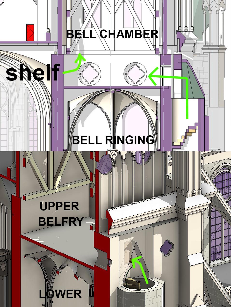
I should mention the belfry.  The lower belfry has an eight-part vault like the ground floor below it.  Was this the bell-ringers chamber?  If so, how do the ropes get down?  There is a single circular opening in one of the vault segments, but no signs of ropes in the images I have seen. The upper belfry actually houses the bells, suspended in a huge wooden framework which rests on a ledge in the stone walls.  Once again, these frameworks are out of date.  They need to be enlarged to fit the ledge that has been formed on all four sides in recent weeks.  The frame should lean in a little so that it is well clear of the walls and able to sway freely under the enormous loads imposed by the swinging of the bells.


All the time, when doing this work, modelling is interleaved with research and review.  Many members of the team have contributed to our collection of reference material stored in the cloud where we can all access it.  In my case it is synced to my laptop hard drive, so I can reorganize the folders and add new material in the usual way, knowing it will synchronize in the background.


Screen shots from drone footage after the fire reveal further differences in the bell towers. Both towers have rear facing windows lighting the lower belfry, but the smaller tower has a much larger window.  A fascinating set of drawings pick up the passage behind the gallery of kings.  The drone footage also shows the three doors that connect the “sky-terrace” between the towers with the roof void, or what used to be a roof void.  The side doors lead to the external walkways, running along the eaves, via a few wooden steps and a doorway. The central door would have led to a wooden “gang plank” which travelled all the way down the centre of the nave … the roof void above the nave actually, and slightly off-centre.


Talking about “off-centre” … the entire cathedral is full of slight shifts and irregularities.  We haven’t tried to reproduce all of these exactly.  We don’t have the information to do that, and I imagine it would take 3 or 4 times as long to achieve it. Our approach has been to start with a completely symmetrical and regular building, then gradually introduce the irregularities that we think are most significant and interesting.  Here and there it is necessary to introduce skewed lines to accommodate shifts in axes, but for the most part we have kept everything orthogonal.  Maybe that will change at some point, but there are much more urgent tasks to tackle.


A while ago I watched YouTube footage of Assassin’s Creed gameplay … a fascinating model, especially if you know the building well.  There are steps over the roofs at the ends of the transepts that bear no relation to reality, but it IS a computer game, and they have been quite open about making inventive changes that enhance gameplay.  Looking at the model and noticing discrepancies or other oddities has helped me to dig much deeper into the design.


I’ll finish this post with a different approach to the cutaway views of the towers. Maybe it needs animation.


Sunday, May 3, 2020

CHIPPING AWAY WITH THE BIM CHISELS


Recent work, leading up to and overlapping with this lockdown period.


First of all, a cut through the nave, where it meets the crossing (image below).  We are looking East.  I have implemented the “flying arch” that we first noticed in a recent post.  Straight ahead you see "door 1" that leads outside from the end of the triforium gallery.  On the left, "door 2" which takes you back into the building, and via some steps up to the bridge that runs across beneath the North rose window.


Then at the base of the two corner columns at the east of the crossing, a more careful setting out of the clustered ribs.  Higher up these ribs belong to the various arches that sprout from the columns in different directions.  Modelling the lower portion as a single element helps during the setting out process, and also results in a cleaner cross-section in plan views.


Switching to the bell towers at the west end.  There are spiral stairs projecting out to the north and south that lead up to the base of the bell chambers.  From there you have to transfer horizontally to stairs in the corners of the upper towers than end at roof level in cylindrical structures with conical roofs.  Quite a bit of trick modelling to fit these in.

Then at the back corners of the towers, adjustments to the buttresses creating a more continuous slope stretching all the way down to the roof over the aisles which must drain through the base of this “canyon”.


This shows up clearly in the next image, an annotated Enscape3d render.  


1)  tall thin windows inserted on the north & south faces of the towers. 

2)  the “canyon” 

3) & 4)  increased depth higher up on the buttress family, to create a more even stepping effect.


Next came modifications to the three door families that represent the portals of the West end.  More of a minor upgrade than a complete overhaul.  Just hinting at the division into horizontal bands with different treatments, and defining a “lintel” band below the tympanum. Not yet ready to tackle the figurative sculptures that give these three entrances such intensity of artistic and spiritual expression.


Always good to pause and view the model in Enscape3d.  In the lower portion you can see the more elaborate versions of the four sculpture niches that help to express the buttress positions.  I do love the ease with which you can vary the time of day in Enscape. I have always admired the way that buildings seem to glow in those brief moments after the sun has set and before the full darkness of night descends upon us.


Probably good to end it there.  Save something for the next post.


Sunday, April 19, 2020

YEAR OF THE DAME


I keep promising myself to write short, punchy posts so that I can publish twice a week.  Not happening.  Seems like I have been working on this one forever.  It takes the form of a retrospective.  One year in.  Project Notre Dame.  An accident of history, voluntary collaboration, "BIM pencil initiative", journey of discovery.


Just over a year ago I was recovering from an operation. The problem had cropped up while visiting the UK and I had the operation there, while staying with my son. During the course of one weekend, we had visited Winchester Cathedral, a concession to my obsessive interest in Old buildings.


Recuperating back in Dubai I had the idea of making a rapid BIM model of the cathedral. I allocated a single day to the task and my goal was to probe my understanding of "how the building works". Sketching and modelling are ideal complements to live visits, backed up by research, image gathering and periods of reflection.


The process of constructing a diagram with your own hands, forces you into a different mode of attention. You are compelled to ask questions and resolve anomalies.  Put simply, it's "learning by doing"


Revit is my tool of choice, my BIM pencil, the familiar friend which has become an extension of the hand-eye-brain loop, familiar to all artists.  When I was working as a bricklayer, in my twenties, the trowel became part of my body.  Most people have developed a similar relationship with a pencil.  You don't have to think about how to hold it. You just immerse yourself in drawing or writing.  That's why the "BIM pencil" metaphor works so well. 


From the time I got my hands-on Revit I was motivated to use it as a thinking tool to search for the BIM equivalent of a freehand sketch. Thinking on the fly, engaging the intuitive, subconscious areas of my brain.


Then a strange coincidence occurred. Notre Dame caught fire. How odd that a Gothic cathedral should hit the news so soon after I had grappled with the form of another, of similar age and size. I couldn’t resist the temptation. This time I gave myself a full weekend, and I was able to reuse some of the parametric families from Winchester, simplified pointed arches and windows.  Along the way I shared two images to Linked-In, the first of these receiving 11,000 views, which was way more than my previous record.


It’s interesting to recall what I wrote when I shared the first image:  


“Half a day spent massing out Notre Dame in Revit, then linking in the Winchester model from last month. Will try to push it a bit further tomorrow…  It’s just an example of learning by doing.  One model prompted by a personal visit, the other by international news.”

And the second one:


“Still very crude and simplified, but starting to get an understanding of the interior space. #notredame is such a symmetrical and regular design for a Gothic building.  Fascinating.  If people are interested in building a more accurate and detailed model by way of open collaboration, maybe this first roughing out could be used as a basis …”


The fire broke out on a Monday night.  I worked on the model over a three-day weekend (Friday-Sunday) and converted this work into a blog post by the following Wednesday.  Two long-standing friends (Alfredo Medina & Paul Aubin) contacted me around the same time, offering to join the collaboration.  


By the beginning of May I had set up a Slack group and we were a team.  Marcel Rijsmus started working on the roof trusses and Daniel Hurtubise joined in the fun from Paris.  Since then at least 50 people have contacted me showing an interest in contributing.  Some made a start but found it difficult to allocate enough time, others never really got going.  That’s fine.  My enthusiasm often runs far ahead of my ability to deliver.  


Here is a view of the current model with some of the major modelling contributions (far from exhaustive, and thanks for everyone who has chipped in so far)


In this project my role has tended to be that of pioneer: forging ahead to map out the territory that we are hoping to inhabit.  Others have then picked up specific tasks and developed them in more detail.  Daniel has done some modelling but contributed mostly in terms of model management and guidance.  He has been invaluable to me as a “shoulder to lean on”.


Paul and Alfredo made major contributions over the first few months but have since taken more of a back-seat role, under pressure from their day jobs.  We began with a strong North American bias to the team, but more recently the centre of gravity has shifted to France, (appropriately enough.)  Of late Nader has been doing excellent work seeking out information and making connections to other groups.


Over the months I have come to realise that Notre Dame has been modelled many, many times using different tools and materials, with different purposes in mind.  There have been film sets, model kits, a wooden maquette that stood inside the cathedral before the fire, several point clouds (including the well known 2012 version by Andrew Tallon) … You can go on to platforms like Sketchfab and orbit around models of the whole cathedral... and of various parts.  Some of these are based on photogrammetry, others clearly “hand-built” using mesh modelling software packages.


Our Lady is a subtle and complex creature.  We continue to discover surprising subtleties as we proceed further along our adventure.  It’s no surprise that most models miss the way that the Triforium galleries turn the corner at the transepts.  That was one of my earliest "AHA moments" and those four locations have been a constant source of new insights, each of them subtly different in its complexity.


Almost everyone stumbles with the setting out of the bays around the apse.  Thirteen bays on the outside, centre of arc offset from the grid, zig-zag vaults to handle the transition from two bays one side to three on the other.  The primary buttresses are straight, radiating out from the 6 columns that define the 5 inner bays that curve around the east end of the choir.  Intermediate buttresses change angle half-way in.  This is one of several discoveries that haven’t yet made their way into the model.  Much still to do.


But let’s go back to the beginning. Sitting here, confined to my fifth-floor apartment in a suburb of Dubai, April 2019 seems a lifetime ago.  Before embarking on Project Notre Dame, I had spent more than three years recreating the Bank of England, as it was 200 years ago when Sir John Soane retired.  This lost masterpiece had been the subject of a competition which so gripped my imagination that I couldn’t stop working on the model when the allotted period expired.


My first blog post for Project Soane documented the approach I intended to take.  For me, drawing and modelling are extensions of my brain, activities that nurture understanding. The building was still a mystery to me, a black box.  I had plans, sketches, photographs … but how to make sense of them? What was the logic behind the layout of the building, the internal courtyards, the subtle angular shifts between different zones? I knew that Soane was the third architect to work on the building complex, but what was the sequence?  How did the plan evolve?  Who did what?


My strategy is always to jump in feet first, engage with the materials, build something, stand back and review, embark on a second wave of building, reflect some more, and so on.  Certain phrases from that first blog post stand out.  “Broad Brush” … “giving it my best guess”


Project Soane was a seminal experience for me.  I had built Revit models of many historical buildings before, with the same goal of expanding my understanding of how they worked, but this was a much deeper dive.  Also, for the first time, there was an element of collaboration.  This was the initial premise of the competition, and continued throughout (although not to the same extent as Project Notre Dame)


In January 2019 I wrote a post called “Ellipse in Residence” which records work I was doing to flesh out the interiors of the Residence Court. Sadly, some of this work has been lost in the bowels of BIM360.  It would probably take 2 or 3 weeks to restore the lost work, but for the past year, Project Notre Dame has taken priority.  One day …


During January and February, I was on sick leave and took a break from Project Soane. It seemed like a good opportunity to explore classical ornament, something which is quite challenging to represent within a Revit model.  I did some hand sketching of acanthus leaves and used these develop some new strategies for generating Corinthian capitals.  All this is recorded in blog posts.  


Some quotes:


“What will we do when robots and AI take over our day jobs? I would devote my energies to exploring the history of “the way we build” using my BIM pencil”


“Can we narrow the gap between fast, intuitive sketching and the cumbersome world of BIM?”


Then came the fire. 

One year on, and why are we still doing this?


For me it’s partly habit.  But beyond that … I continue to learn.  Just a few days ago, I discovered that the spacing of the timber roof trusses is much closer than the spacing of the masonry columns. As I write this post, I am watching a two part documentary on YouTube.  The channel belongs to Deutsche Welle (German Wave) an independent public broadcaster. But the production is credited to Program33 a French company which describes the film as “historical docu-fiction.”


How much of the story is “poetic licence?”  That’s an interesting question to hold in the back of my mind as we continue our work. I suspect that a generous dash of “human interest” has been added to the story line but it remains an impressive achievement, well worth watching.


I love the short clips of real artisans working with the techniques of the time.


https://www.youtube.com/watch?v=u7W9PwzZtzU


By the way, as we discovered a couple of months ago, the North Tower should be about a metre wider than the South Tower … resulting in 8 statues in that portion, not 7.  I find it oddly reassuring that even lavishly funded enterprises make mistakes when modeling a building of this size and complexity.


The other contributors have chosen areas of interest, and devised their own approaches to the project.  Levels of activity go through natural cycles.   


Another quote from my Linked-In bulletins about Project Notre Dame.  


“I try to apply my BIM pencil as a Renaissance sculptor might apply her chisels … as I look for the natural mode of expression, hiding inside my chosen tools.”


The image below was created by sequential use of three of my favourite chisels (Revit, Enscape3d, Photoshop)  It tells a story about changes that were made, three or four generations into the building process.  As the gothic style progressed in time, builders become bolder, windows larger, light more pervasive.  There is a note of timidity here.  The end bays of the nave were left in their original state, with smaller windows above a portion of the original roof.  


There is another layer to this story.  Bay no 8 is next to the transepts, where the triforium galleries wrap around.  On the inside of each corner there are 3 façade bays, with round windows that give borrowed light to the roof voids.  Six dark roundels then on the two corners that form the West flank of the transept.  


But on the East, those six roundels allow light into the cathedral, directly from the outside.  It seems that this arrangement can be credited to Viollet LeDuc, who renovated Notre Dame in the nineteenth century.  But I  still have doubts about the state of these bays before he modified them.  Were there roundels on the East and blank panels on the West?  Were there full-height windows on the East and blank panels on the West?  The documentary suggests full height windows on both sides.  But why did he change these?  


These conundrums have a habit of resolving themselves over time.  A luta continua.  The struggle continues.


Saturday, March 28, 2020

OFF THE GRID


For some reason I started watching YouTube videos of Notre Dame again.  I came across one (in French) that deals with renovation activities from six or seven years ago.  There is a great sequence that shows the casting of a set of new bells.  It also deals with improvements to the organ, including the new console which Ryan did such a good job of modelling.


https://www.youtube.com/watch?v=Sw6Q8cuWn1Q&t=972s


I started to notice fleeting glimpses of areas that have intrigued me, so I kept hitting the pause button and taking screen shots.  There are steps where the aisles of the choir hit the curve of the apse.  It’s very difficult to get a clear view, because the flying buttresses get in the way.   I was aware of this step, but I hadn’t realized that it contained little rows of windows.  Something similar happens along the nave, but at a higher level.  That was a mystery at first until we realized that the clerestory windows had been enlarged at a later date.  Maybe the step in level where the choir meets the apse tells a similar story.


The next one was really exciting to me.  Some guys are threading a big flexible pipe out of one door and into another.  This is at the NW corner of the transepts.  I’ve been looking for a view of this area for a few weeks now, to confirm my idea that the door above the short flight of triangular steps leads to the bridge across the North transept, (below the rose window) by going outside and back in again. 
 1 = the door at the top of the steps.  
 2 = a small door I was unaware of that seems to lead into a square “chimney” which remains somewhat mysterious to me.  
 3 = the door leading to the bridge, and
 4 = an arch that seems to be propping up that chimney.  This is also completely new and unexpected to me, even though I’ve been working on this model for almost a year.


So there are some changes here that need to be made when time permits.  The arch is fairly straightforward.  (1) but the roof needs to be raised and converted into the “flat-stone-slab” type.  I’m not quite sure how that works and what the knock-on effects are for the windows below and the vaults over the chapels, which relate to the windows on one side and to arches into the outer aisle on the other side.  I had assumed that you would have to go down some steps to get to the roof surface and back up again to access the door to the bridge.  An interesting puzzle to tackle there.


So what about the title?  The literal meaning refers to the distortions in the floor plan.  Could we actually reflect this in our Revit model?  A bit of drafting to explore this.  Looking at floor plans, sometimes they have been straightened up.  Sometimes they seem to bent at the crossing, like a broken backbone.  Lying in bed one night I got the idea of creating the choir as a separate link and rotating the whole link by a degree or two.  But it doesn’t work.  The distortions are more complex than that.  


I drafted out a skewed grid that seems to work quite well.  But decided against trying to implement it.  It’s still a simplification of reality, so we might as well use a simplification that makes modelling a lot easier (an orthogonal grid)


Another thing I’ve been doing while lying in bed is to practice inventing ornament (leaves and scrolls) by drawing on my phone.  I was inspired by some YouTube videos that I watched, but rather than copy something, I just adopted the general idea and improvised.


Back to vaults. The sexapartite (sexa/hexa whatever) vaults that I made long back are a bit of a mess.  I have a much better cross vault family based on spherical geometry, so I can use this for the man span.  Then I can construct the two side arches, plus the big arch across the middle.  Took a while to figure out the geometry and convert it into formulas, but I got there


That’s as far as I could get with the traditional family editor.  The side vaults are kind of like the zigzag vaults around the apse.  So I decided to use the 9 point adaptives that I had used there.  


That worked fairly well, but I had to repeat the same sequence 8 times, and they tend to click onto the wrong edge … because the ribs have lots of parallel edges.  But at least you end up with a family that adapts to different widths and depths


That as long as it remains regular.  Ie the two side arches have to be the same size and everything must be orthogonal. That won’t work for the transepts because the aisles to the west are different widths compared to the ones on the east side.  Basically, we need to “fake” the skewed grid in some way.  My solution (for now) is to rotate the centre rib slightly.  So I have a second version of the family that handles the transition across the transepts caused be the different aisle widths.  It’s a cheat of course, but it works quite well.


While I was working on this, Nader popped up on Slack talking about a book by Andrew Tallon that he had acquired.  He’s the guy who scanned the cathedral about 12 years ago.  He was a Belgian/ American academic who died somewhat tragically in 2018 and scanned many gothic cathedrals.

In this book there is a colour coded diagram that indicates when different parts of Notre Dame was built.  I think this must have been created by a graphic artist because, although it picks up the skewed grid quite well, other aspects of the drawing are quite inaccurate.  It’s fine for the purpose intended though.  It’s quite interesting to compare it to a much older drawing that I found on the internet when I first started working on Notre Dame.


More interesting are some images taken from the point cloud.  At the moment I only have some slightly distorted images taken with a smart phone, but they still provide useful insights. 


It’s quite interesting to reflect on the various activities that combine to form the experience of Project Notre Dame.  There are days of intense modeling activity.  Periods of sifting through source material and comparing it to the model.  Times when the information coming in seems to undermine all the progress to date.  Weekends when I can’t resist going off at a tangent.  


The cumulative effect is a very rich tapestry of background familiarity.  Looking at new photos I quickly realise just where I am in the building and what I expect to see.  New insights pop out from the background and tap me on the shoulder ... "hey look, you didn't notice me before!"