Saturday, March 26, 2022

RUSSIAN ORTHODOX


We make choices all the time.  What is the appropriate Level of Detail for this element?  How can I capture the essence of what I need to convey while remaining lightweight/agile?  How can we best empower the world with energy? 

Personally, I feel that Nuclear Energy should be energetically pursued in parallel with other technologies.  Paradoxically, the “zero risk” narrative that seems to have gripped the west, has increased our risk exposure via dependency on less cautious powers to the east.  Small is beautiful, but sometimes we need the economies of scale. 

Fossil Fuels have pulled more people out of poverty than any other human technology. Yes we have to transition. 100 %. But in a panic? With a one dimensional narrative and tunnel vision? Did that serve us well during the covid experience?


I have been learning about Eastern Orthodox churches.  There are many variants: from Venice to Constantinople; Athens to Kiev: Moscow to Frank Lloyd Wright.  This post looks at one small church is what is now Russia, but was once a Viking dependency, often referred to as “Kievan Rus.” 

One feature of churches across this region is the “Onion Dome.”  They come in various shapes and sizes, so why not choose a “scalable” approach to modeling?   Revit handles scale differently from CAD. Global scale would be nice at times. It's available with the “planting hack” but why can't we have a Generic Model template that works like that? Maybe a check box option, like the ones we have for

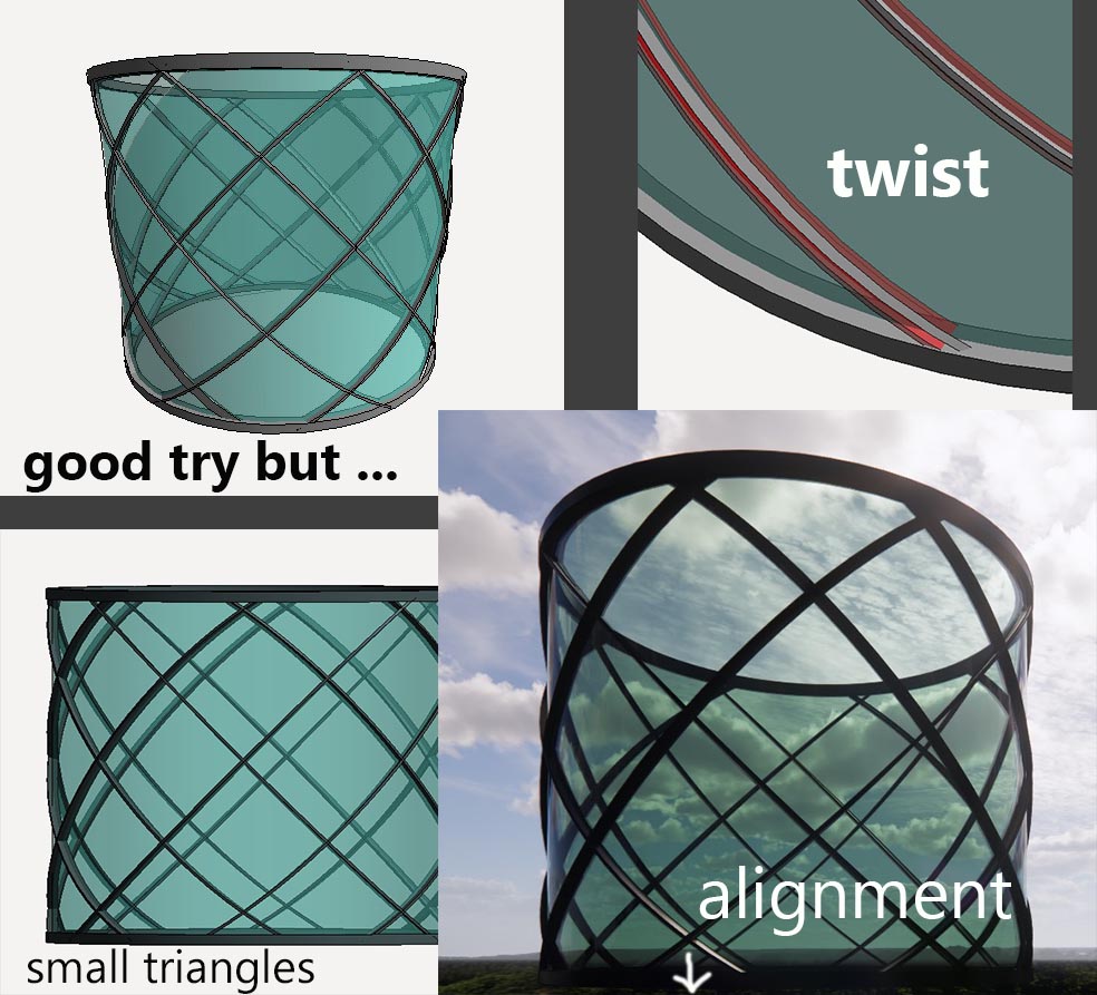
One neglected feature with scaling potential is the spline. There are two ways to drag the ends of a spline, mediated by use of the “Tab” key.  Tab-select will allow you to move the end point independently.  Normal select will scale up the whole line.  Constraining the ends of a spline in family editor gives the scaling behaviour. 


Eastern church plans tend to be “centralized.”  There are polygonal versions, and “tetra-conch” typologies, but here we have the “Circle in Square” archetype.  I realized a few days ago that this has much in common with Palladio’s famous Villa Rotunda.  Different function, different context, different stylistic period but the plan geometry is related.  Think of it as a kind of “noughts and crosses” game

(Tic-Tac-Toe).

 Often this plan form is elongated in the vertical dimension.  Also the east end tends to be developed into a “trinity” of apses. Probably with a larger central bay although here the size difference is very subtle.  The four stout piers supporting the tower and dome, transition via pendentives in a very simple and satisfying way.  That was fun to model as a nested family.


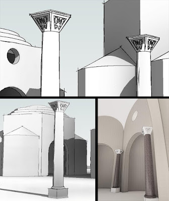
The scalloped-edge wall termination is also very common.  In this case there are projecting rain spouts and the low points, diagonal at the corners.  These rest on slender column clusters, attached to the wall surface, once again accentuating the verticality.


This is all modeled as a single Revit Family, for inclusion in my collection of churches and temples.  So the walls cannot be system families.  They are just dumb extrusions.  I remember as novice Revit user, wishing that we could use a version of the wall tool within Family Editor.  I was trying to create planter boxes with integral seating: standard elements which were repeated several times across a landscaped deck.  I wanted the wall behaviour with multiple layers of material, joining behaviour and simple height controls.  But I also wanted the stability of a loaded family.  Groups were giving me a lot of grief with junctions misbehaving and mirrored versions doing weird stuff.

Anyway, the point is that my “windows” and recesses here are “face-based” families, so that they will host on and extrusion.  It’s not perfect, and I had to make the placeholder extrusion that comes in the template much larger.  Families will break if one of the types has a void that completely destroys that placeholder extrusion (or wall in a wall-hosted family)  This can be very confusing.  Within the project everything seems fine.  You are placing the “window” on a surface with plenty of room.  But it refuses to form (“cannot make type …”)  No clues given as to why. 

Just make sure that the host geometry in family editor is bigger than the largest type you are going to make in the project


The whole church sits on a square mound.  I have represented this as a stepped platform.  This is not about faithful modeling of a particular church.  I am analysing the evolution of form across space and time, learning how religious architecture responded to the needs of different human societies.  So there is a judgement call.  Like I said at the beginning.  What is the appropriate level of detail?  How can I use modular components to help the work move forward effectively?


This example uses six or seven nested components.  I made them quickly.  This is “BIM sketching.”  I am trying to think of the fly and avoid getting bogged down.  Aiming for the fluidity of freehand drawing while employing the power of digital tools.  If I get too deep into the weeds, I will lose the ability to see my work in the context of human history.  I may be tapping into my inner Revit nerd, but I am also reflecting on seven decades of life, evenly spread across three continents.  I want to stand on the shoulders of giants, to find my place in the thousands of years of human history leading down to this moment.

We need to respect our ancestors. They used fossil fuels to power the industrial revolution. It was ugly at times. Human beings are deeply flawed. But ultimately it delivered huge advances in health care, sanitation, nutrition, lifespan, universal education. The burdens and risks that motherhood gave to women have been lifted to a remarkable extent such that they can choose to work in almost any field. They have consistently outnumbered men at university for many years now. 

Progress is a double-edged sword.  Beware of simplistic answers.  Suddenly we realise that demonizing “fossil and nuclear” has had the unintended side effect of outsourcing our risks to others.  Our wish to be “uber-ethical” has made us vulnerable to less-scrupulous actors in the game of history.

“Just thinking out loud” to quote a young Jamaican lady who made some very interesting YouTube videos a couple of years ago.


Friday, March 25, 2022

BEAM OF LIGHT

Is AI good or bad? Do lock-downs work? Have we forgotten how to do nuanced risk-benefit analysis?

It's easy to criticise Putin if you live in the Western Quarter of the Global Village, but harder to query the dominant narrative about other topics. How could you possibly speak up for Fossil Fuel or Nuclear Energy? Why express reservations about the runaway train of Diversity Worship?


As a painter, musician, designer, I face the challenge of navigating a route between variety and cohesion.  I value diversity, but I also value its opposite.  My task as an artist is to strike a delicate balance. But what about public life in a typical “liberal democracy”?  Is a balanced view even possible? How can we swim in the frenzied currents of polarised politics, torn between the opposing poles of "woke activist" and "right wing bigot”?  Words become weapons, their meanings carefully framed. 

Why would we want to “Capture” Reality? What would the polar opposite approach to this be?  I like to think of my BIM pencil work as "Releasing Reality," not enslaving it: like Michelangelo, liberating his statue of David, trapped inside a block of marble. The tunnel vision approach of reproducing the surface appearance of "Heritage Buildings" does have some value of course, but I worry that it obscures the deeper vision of a search for meaning by means of analytical studies. 


So, I stumbled into this modelling query on Linked-In.  It’s a lighthouse.  Beacon of light to save mariners from floundering on the rocks.  How do you persuade a sweep to wrap itself diagonally around a cylinder?  “That’s why we don’t use Revit” opined one voice.  You’ve got to love engineers.

I remembered a post I did many years ago, (2013 in fact)

https://grevity.blogspot.com/2013/06/making-glass-onions.html


So I created a cylinder and cut it with a diagonal void.  Now you can use “pick-edge” to create a path for the sweep that will represent one of the diagonal mullions.  


Now I remember why I used a circular profile in that old post.  Call it the “twisting problem”  You can’t get both ends of the sweep to penetrate the cylinder at right angles. 


Even worse, when you create a radial array the angles twist further around as the array progresses.  I guess they are all trying to relate back to the original edge that gave birth to their sibling.  Something like that.

Issue no 1 can be tackled by using a swept blend.  Now you have two rotation parameters.  Give them different values to maintain the relationship from top to bottom of that first diagonal mullion.  It almost works. 


Unfortunately, as the difference between the two angles increases there comes a point where the vertices jump their connections.  Now the short side is morphing into the long side.  It’s very weird and difficult to capture in a screen shot.


Now in a simple “Blend” you have an option called “Vertex Connect” which is quite cute. You can do a manual over-ride to tell Revit which corner connects to which.  I had never looked for this in a “Swept Blend” before.  But there it is!  Wonderful.  And there’s a quick fix using “Twist Left” or “Twist Right”. 


The second issue is solved by saving a single diagonal mullion as a standalone family and then nesting it back into a second family before creating the array.  Much more stable.  The path takes its host edge from the nested family. The array process in the host doesn’t filter down to affect work-planes in the nested level.

I need the mullions to start and stop neatly at a horizontal band at the top and the bottom of the glazing.  So I create a cylinder in the mullion family (set to invisible) and eight vertical lines (also invisible) around the edge.  While editing the swept blend, you can drag the end points of the path.  It will remember the curve of the original edge, even if that geometry was deleted.  But you can manipulate the length.  So now I can get the mullion to go from the base of one line to the intersection with the “next but one.”  In other words it’s doing a quarter turn (90 degrees)


It soon becomes obvious that the height of the glass needs to be equal to the length of the chord of this angle.  You can get this by Pythagoras or Trigonometry, but I just drew it in plan and set the height to the nearest millimetre.  Now you can fine tune the end angles to stop and start in a horizontal plane (check this in elevation)

I did the glass as a continuous thin-walled tube, but there are only two sizes, (three if you count the upside-down triangles as different) So it should be easy enough to create the individual panes as nested components also.  I guess you could figure out how to make the whole thing highly parametric so you can type in whatever size and proportions you need.  I think I will rest where I am though


An interesting exercise.  Learnt something new about swept blends. Brought back memories from almost a decade ago.  Reminded myself that democracy, for all its faults and frustrations is a beacon of light to the world’s floundering ships of state … 

if only it can recover its self-belief !

family link below. just one way of doing it.


Lighthouse 04.rfa


Sunday, March 13, 2022

BYZANTINE COLUMN

 Byzantine columns are interesting.  There is some kind of relationship to the classical orders, but the feel is very different: less refined, kind of rustic, more carefree perhaps.  There is a tracery feel to the motifs in contrast to the crisp, sculptural, geometry of the classical orders.


My modular system for generating columns uses the scaling behaviour baked in to the Planting category.  This has its shortcomings.  The levels of nesting can get a bit too deep.  But it's a quick way of leveraging previous effort to create new variants which can be sized to whatever situation could arise, from window jambs to Nelson's column.


My first attempt at a Byzantine capital is designed to allow for several variants.  The core geometry is a blend between a circle and a rounded square.  To make this work you need to split the circle into 4 quadrants.  The faces are not truly flat, but they are flat enough to stamp out a pattern using a profile with a short path.  This means I can develop several different profiles and swap them out.  I'm not trying to reproduce anything specific here, just aiming to capture the "feel" of Byzantine.


The base, shaft and capital of my columns all have rectangular void extrusions which enable easy generation of "types" for half, three-quarter, & corner columns.  That behaviour took a little time to set up, but transfers fairly seamlessly to each new variant. Long story short, I got my first byzantine column family for very little extra effort.  

Moving forward in baby steps.  Nothing wrong with that.