Showing posts with label Musharabiya. Show all posts

Saturday, August 15, 2020

CLASSICAL XMAS MUSH

It’s November 2012 and I’m all pumped from winning the Parametric Pumpkin Competition for the second time.  That was my Arcimboldo style witch’s head … assembled from vegetables.  Zach Kron, who came up with that competition asked me to do a session on Vasari Talks, a series he was doing with Lilli Smith.  Remember Vasari?  I used it a few times.  The built in solar diagrams and wind animation were useful. 

They asked me to do a demo of the “wig-hat” which was the witch’s hair, assembled as a repeater using spring onions … was it a repeater?  Seems like the recording of my talk is no longer available on that link. 

After the demo, I showed a few images of other things I had done using the principle learned while making vegetables.  I wanted to assure people that my explorations were relevant to the “day-job” world of Architecture & Construction.  This is where I first developed my early concept model of Oscar Niemeyer’s Brasilia Cathedral: fully parametric, as they say.

I also showed a model of the Dubai Creek Golf Club, probably the best-known design by my boss, Brian Johnson (it features on the 20 Dirham note here in the UAE).  One of my first attempts at an adaptive component: three instances, one for each “sail-shaped” roof.


https://grevity.blogspot.com/2012/11/webcast-tonight.html


This is around the time when Paul Aubin and I started communicating directly with each other.  He was working on a Corinthian capital which totally blew my mind, but also challenged me to think about how I would approach this challenge. 

“How can we possibly standardise and parameterise all that variety ?  And even if we could, where would that get us?  The spirit of the Corinthian seems to live in it's infinite ability to be constantly re-invented.  How do you factor that into an equation?”

I the second half of the post I attempt a stylised version of Corinthian made from brass plate, cut and folded into shape. Designing directly in Revit. Of course in the good old days, there would have been a symbiosis of architect and artisan when conjuring up classical detail, both contributing their skills, experience and sense of proportion.  How should that collaboration play out in the digital era?


https://grevity.blogspot.com/2012/11/desert-classic.html


In the next post I attempt to take a leaf from Paul’s book and create a fully volumetric stone version of the Corinthian capital. It’s fascinating to compare Paul’s approach and mine.  He came at it very systematically, basing his work on Robert Chitham’s excellent book “The Classical Orders of Architecture”

I just jump in and start thrashing around, taking liberties and shortcuts wherever the mood takes me and feeling my way to an acceptable interpretation of the genre.  I was very concerned with “RIGS” at the time: arrangements of reference lines that can be resized parametrically.

There were several iterations before I arrived at my current system for mix & match, scalable classical columns. 


https://grevity.blogspot.com/2012/11/a-new-leaf.html


The next post is quite interesting because someone has posted a Revit version of the Pantheon on LinkedIn recently.  He has taken it a fair bit further than I did.  I toyed with a couple of ideas for representing Corinthian here, including symbolic lines that only show up in parallel views. As usual I am trying to use Revit as my BIM pencil, and extension to my brain, a tool for better understanding how a building works: spatially, structurally, stylistically …


https://grevity.blogspot.com/2012/11/pink-pantheon.html


More rigs and more attempts to explore “the way we build”.  I had extracted a lot of mileage from a “Rectangular Rig” so the question was, would an extra dimension create new possibilities or would it simply complicate things.  The first set of explorations were good fun but didn’t produce anything that I regarded as a significant breakthrough.

At the end of the post I show an image of a Bavarian Baroque church.  I was looking for challenging geometry from our built heritage that might prove amenable to the techniques I had used to create vegetables.  I never got far enough with this model to test that idea out.  Would I be able to represent the free flowing curvature of the ceiling vaults in a convincing way?


https://grevity.blogspot.com/2012/11/cube-rig-blues.html


December now, and an explanation of how I created my abstraction of Niemeyer’s cathedral.  I gave some examples of what happens when you play with the parameters. Vary the number of legs, the angle of slope, the heaviness of the legs in relation to the overall shape. 

Does this kind of “generative form finding” work better than the “artists eye”?  Stupid question perhaps.  All depends what you are trying to achieve.  Whatever too you decide to use: digital or analogue, computational or intuitive, rules based or touchy feely … you need to pay your dues.  If you want to achieve something worthwhile, first acquire a level of fluency with the chosen tools.


https://grevity.blogspot.com/2012/12/cathedral-of-light.html


The first ever AUX in Dubai.  My session was about massing. “Concept design … clarity of thinking … strip away the irrelevant detail … can you capture the essence of the design problem?  … We need to use BIM tools as we would use a rapid pencil sketch”

Looking back, I’m really impressed with the way I prepared for this session, and the balanced structure I devised: a few slides, then a demonstration sequence, and closing with a longer slide show.  This was very early in my career as a public BIM personality.  I have come to realise that my contribution doesn’t always appeal to mainstream audiences.  So be it.  I get enough positive feedback to realise that I am doing something important and useful, and I’m doing it “My Way”.

https://grevity.blogspot.com/2012/12/aux-dxb.html ...


I have always been somewhat ambivalent about Autodesk University.  The name is just a branding decision, I get that, but my idea of a university is much more open ended and exploratory that this industry convention.  The next post includes quite a lengthy rumination on the global politics of technology and the need to better integrate our heritage of intuitive hand-crafted ingenuity with the digital sphere that offers so much power.  Power can cut both ways. If it doesn’t mesh with our traditions.

“The main reason I'm hooked on Revit and BIM has nothing to do with ROI or clash detection.  It's a better way to draw.  And drawing has nothing to do with lines, arcs & circles.  Leonardo wasn't thinking "now I'll draw an arc".  He was exploring how the human body works.”


https://grevity.blogspot.com/2012/12/hey-you.html


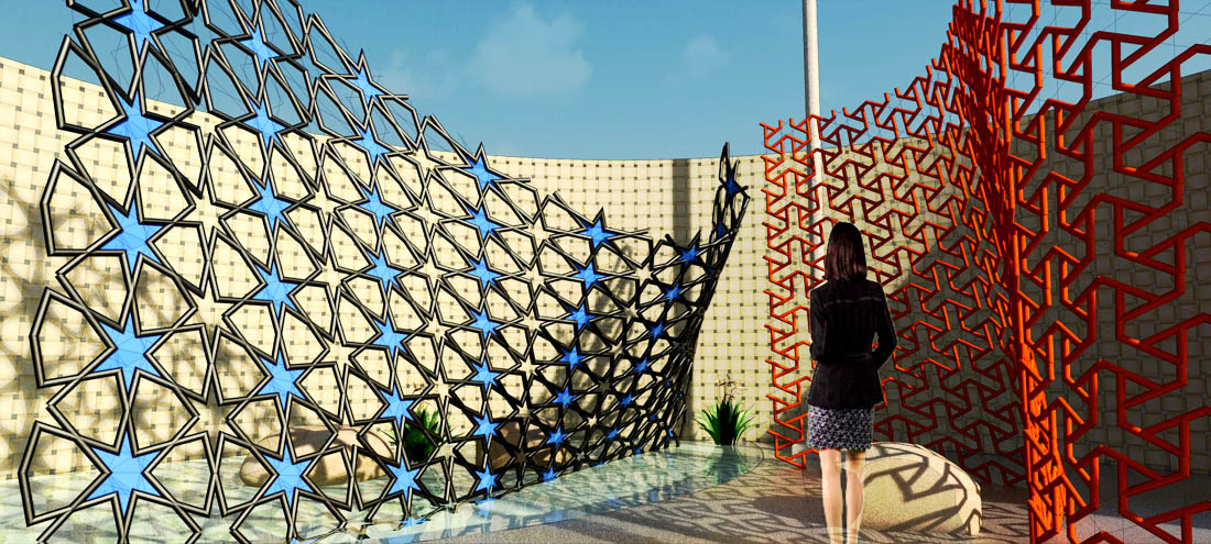
And so to Xmas 2012, and the “Mush” part of my title.  I figured out an approach to making Arabic patterns that will populate divided surfaces.  This allows you to create Musharabiya Screens that twist and curve.  Creating each new curtain pattern family is a bit tedious, but once you have a small library of these, it’s very easy to create screens of different sizes, shapes and proportions. 

Since then I have developed other solutions: scaling patterns up with the Planting Category hack for example.  But maybe I should give this one another run around the block.  What would I do with it now, almost 8 years later?

https://grevity.blogspot.com/2012/12/xmas-mush.html


Wednesday, July 24, 2013

SCREEN PLANTING

Lots of people to credit here, but I'll point the finger at my good friend David Light and this recent post.      EMPIRE BIM

Each to his own, and as it happens I'm not particularly addicted to Star Wars. Maybe it's a generational thing.  But if you've followed this blog for any length of time, you'll know that I do have a thing for Musharabiya screens.


Make a new family, starting from a "Planting" template.  Go to the front elevation, use reference planes to mark out a square.  Mine is 1m x 1m. Make an extrusion within this square.  I started with something pretty boring, impatient to see results.  Nest this into another planting family & position at the origin (centre).


Nest the host planting family into a curtain panel family.  Again place at the centre.  Place a height dimension and make it a reporting parameter.  Mine reported 4m.  In type properties, set the height of the planting family to match this measurement.  It will scale, as all good double-nested planting families do.


Load into a project and make a curtain wall type with square panels and no mullions.  You need to size the wall so that there are no part panels at the edges.  I used an 800x800 panel and made the wall exactly 4 modules high by 7 modules long.


Set the panel type for this CW family to the panel family you have just made. Bingo.


Now try halving the module.  Just change the height & width parameters in the curtain wall definition.  All the panels resize like a charm.

Once you get the idea, it is easy to do some recursion.  Select a panel and unpin it.  Use the type selector to replace the panel with a wall type.  Choose a curtain wall with half the module size.  One panel becomes four.  Repeat this procedure to make ever smaller cells.


One of the drawbacks of this kind of blanket scaling is now revealed.  The panels get thinner.  We are back to CAD-style dumb scaling.  The whole idea of parametric modelling was that you had separate control over different aspects of a component.  Change the size of a door without scaling down the door frame or ending up with a non-standard thickness for the door leaf.  In our enthusiasm for clever new tricks we tend to forget these fundamentals.


So what if I wanted all the panels to have the same thickness ?  There is a way, and it's not too hard.  Go back to your original "nested planting" family.  Add a thickness parameter to control the thickness of the extrusion.  Define that thickness as "Height / Thickness Ratio".  Load back into the "host planting" family.

Link the "Thickness Ratio" parameter of "nested planting" to a matching parameter in "host planting".  Load into the curtain panel.  Link parameters again.  Now you can create different types with different "Thickness Ratios"   Basically if you know that the panels is half the size, just halve the thickness factor and the thickness will match the larger panel.


You can achieve subtle variations of thickness now, it is no longer totally dependent on panel height.


I went on to make a few more panels.  This is very easy once you've set everything up.  Just change the name, edit the original extrusion, load back, load back, load back.  Set a curtain wall to use the new panel.


This is the fastest method I have yet found for making a variety of screen designs with a module size that is easily adjusted.


One big drawback though.  You can only have whole panels.  No cutting and shaping at the edges.  Forget it.  Best I can think of is to make all the cut panels separately as Generic Models and place them one by one.  If there are part panels in a horizontal row, Revit will give you baby panels centred, with gaps between, as in the image below.

So it's an interesting technique but time alone will tell whether it will be useful on real projects.  Maybe for early studies where you are experimenting with module sizes.  Then once the module is fixed make families similar to the ones in my second ever post

HERE.

We are still using these.  Done solid service on several projects.  But changing the module size is a bit of a pain. Not too bad, but can't be done in a matter of seconds like you can with the planting version.  So once again, the best method for early design may not be the best method for construction documents.  No surprise there.  Always been the case.  6B pencil versus 4H.  Work smart, be flexible.

Monday, December 17, 2012

XMAS MUSH

This is a continuation of my previous work on Mushrabiya Screens.  It was prompted by a query from an experienced Revit user in our office who was looking to do a scaleable pattern with variable "member sizes". 


First of all you need to choose your pattern and draw it, probably in a drafting view.  Sometimes it helps to trace over a jpeg image.  You need to think in terms of construction lines, which usually means extending the pattern through to the edge of a bounding rectangle.  The goal is to identify the points where the construction lines meet the boundary.


You need the spacing of these points, expressed as fractions of the boundary side.  These fractions will become "normalised curve parameters" in a curtain panel family.


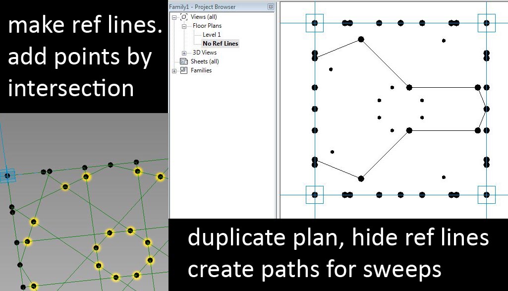
Open up a "curtain panel by pattern" template in family editor and place points along the boundary.  They should be hosted on the reference lines.  Select each point and give it the desired "normalised curve parameter".  Takes a while, depending on the complexity of the pattern.  Now connect these points in pairs to recreate the construction grid.


Convert this grid into reference lines, and add more points.  Select these new points, one by one and "host by intersection".  You can now duplicate the default plan view and rename it.  I named mine "no ref lines".  Under visibility graphics, turn reference lines off in this view so you just see the points.  Now you can creat the original pattern using model lines.  Choose pairs of points and join using "spline by points".  The customised plan view really helps you to see these new lines clearly without the confusion of the construction grid. 


In my example I have 4 paths, each consisting of a chain of 8 lines.  I host a point somewhere on each chain, make it's work plane "visible always", set this as the current work plane, and place a mass profile.  Select path and profile: create form.  Repeat for the other 3 and you have a curtain panel.


New family.  Draw a rectangle in an elevation view.  Add parameters for Length and Height.  Change the lines to ref lines, select the loop and create form.  You get 2 options (surface or solid) choose the surface.  Select the surface and divide.  Load the curtain panel and use it to populate the surface.  You can create parameters to control the number of cells in U & V directions.  In my case I used the same instance parameter for both directions.


Load this family into a project and place several instances.  Vary the pattern scale with ease.
Next I added an angle parameter, again the same for both U & V.  This rotates the pattern within the surface.


My next idea was to use "divide by intersect".  I did this in family editor to create a surface divided into very irregular quadrilaterals.  The panels adapts to these shapes without a murmur. 


Looks a little crazy but maybe that's what you want.


Back to the previous divided-surface family and I added a label for the embedded curtain panel.  Now you can load several different panels and swop them in and out. 


I also have parameters to control the mass profile used in the sweeps.  Now from inside family editor you can select individual panels and adjust how "heavy" the members are. 


I dredged up some of the previous patterns I had made.  I was a bit lazy at the time and used circles for the sweeps, so I went back and replaced these with nested profile families and gave myself the option of switching between circular and rectangular sections. 


Now all the preparatory work is beginning to pay off and I have a highly parametric mushrabiya family.  So I packaged it up as a little christmas present for all my faithful readers. 


Hope you enjoy it. 

SCREEN FAMILY HERE

I am off on holiday now so may not be posting until the new year. 


Tuesday, September 25, 2012

MORE WEB WEAVING

Episode 3 of my current bout of mashrabiya bending exploits.  This one is even more like a spiders web.


I started once more with some drafting to clarify the basic geometry and express it as fractional placements along the edges of a rectangle.


This informs a curtain panel by pattern, to set the positions for placing points (using the infamous "normalised curve parameter" which is an inherent property of points that are hosted on lines in the conceptual massing environment.  Pairs of points are then connected together using spline by points.


More points added and "hosted by intersection" so that they remember their relationship to two lines, even when these lines cross "at a distance" when the panel gets twisted.  All part of the magical points-based geometry that was incorporated into Revit from 2010 onwards.


Connect these in pairs to define the major pattern elements.  Create surfaces and sweeps.


Load the panel into a project then use it on some wiggly divided surfaces.  And that's another one done.  Took about 3 hours this evening after work.

And on the subject of points based geometry, check out Zach Krons video from a webinar he did recently.  From Data to Tada   I watched this last night and it just joined all the dots together nicely for me. I hadn't full understood the different point placement modes before.  Very nicely explained.

Tuesday, September 18, 2012

PATTERNISING WITH THE NATIVES

This post was nudged into being by viewer response.  A couple of comments on my last post with links attached.  Don't know if/when I will ever get around to Rhino/Grasshopper.  I think in the end you have to make a judgement call about where to focus your energies and for me it's less about clever modelling and more about exploring the intersection of ideas. 


The link to islamic patterns didn't really show me anything new, but it did supply the extra impetus to try harder to apply some of these geometries to PBP (Panel by Pattern).  The one I chose has a fairly simple rectangular repeat, roughly in a 5x3 proportion.


A little drafting work on top of a jpeg image gave me some useable spacings for points that can be used to generate a grid. 

There is a lot of hosting points on lines, selecting two at a time, & creating spline by points.  After a while you need to start using host by intersection, again repeatedly.  Eventually I have pieces of reference line that sit on top of the grid and will be used as paths to sweep along a tubular framework.


This involves lots & lots of host point, show reference plane always, set plane, draw circle, make radius a real dimension, apply a parameter.  After a few of these, I discovered that you can copy the assembly of point-circle-dimension into empty space and then rehost the point on a different line.  That's a big time-saver.


Eventually I have a curtain panel that looks like this, which should be testable.


Create an undulating surface as an in-place mass. 


Divide it so that the grid is rectangular in roughly the right proportions, load up the panel and amazingly it worked. 


Definitely worth doing a few more of these.  Took a couple of hours to create the panel, but if I make 3 or 4 of them and put them up for download maybe someone else will pick up the challenge and create a couple.

About half way through I picked up from my stats page that there was traffic coming from Revit Forum.  Following the link I discover people are enjoying my recent posts which supplied the extra motivation to finish off this post.  Sadly the original topic related to another Dubai based firm which has has a failure of nerve in relation to BIM.  Please don't be discouraged.  It's taken me 7 years of grinding away to get to where we are now at GAJ; multiple setbacks, hearbreaks, "is it all worth its".  Fortunately my principal has been very supportive, but it's been hard work with some of the other seniors.  Happy to say that we are now well past the point of no return and I have the pleasure of spending much of my time inducting some very bright young architects from all around the world into the delights of Revit. 


Do not despair.  We are heading in the right direction and sooner or later everyone will have to wake up.