So first of all, I'm in the competition. I have a concept that is strong enough, it's definitely a pumpkin, it conjours up the spirit of Etienne Boullee, it's parametric, and I'm having fun.
At the time of writing this, I have one long weekend plus 2 or 3 normal ones to flesh it out. So what's the plan? Where should I focus my energies.
The central theme is use of BIM for concept design. So don't get sidetracked into resolving minor details or showing off Revit trickery. We have been striking a balance between highly parametric massing families and quick "manual" adjustments, using whatever is most appropriate to current design concerns. Let's continue along that road.
Goals ?
1 I want some compelling images of the gallery spaces within the pumpkin slices that form the base. All we have at present is a schematic section through the lift cores. Need to develop the gallery spaces themselves.

2 We should probably develop the ground plane. Are we going to have crops growing down here, domesticated species on display ? How do I make that not boring ? How do we represent it in a BIM way ? Should we be developing the idea of a basement as hinted at in the octagonal iteration?

3 The interior of the dome/auditorium. How can we make this more convincing, more dramatic ? At the moment it's just a ridiculousy huge volume. What can we do develop this, beyond just adding frills?
4 The question of scale remains. Have we settled on a final size? How do we justify the height of the dome ?(effectively dead space) Isn't there an exercise to be done, creating a fully parametric family that will generate a full range of design alternatives for the client to review ?
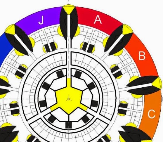
I've shown off a couple of my final images from this session. How did I get there ? I like to do drafting in Revit. There is this strange myth that BIM has to be 3d. Sometimes 2d is the fastest way to explore an idea. Hence my exploration of 9-sided geometry at ground & basment levels. Circular corridors can be very disorienting, so I'm thinking in terms of colours that tell you which segment you are in.
To develop the gallery spaces I decided to bring in a single segment an place real walls & floors. Better perhaps to try this out as a side study first. By chance my single segment came in with a rather small width in relation to its height and depth. An interesting (if unintended) demonstration of the parametric capabilities of this family.

Next problem. Walls steadfastly refused to be placed "by face". I know from experience that walls will successfully attach to much more complex surfaces. Perhaps the problem lies in the sharp points at the ends. I added small voids into the rig to clip these off and hey-presto, walls work. Maybe I will

I had this idea of curving the front edges of the floors so that the gap between floor & sloped glazing varies. I'm forgetting about the musharabiya for the moment. Just treat is as a plane of glass. You don't want to start editing the boundaries of floors generated from mass faces, so I borrowed an idea from my Gherkin studies: shaft openings.

I also had it in mind to use escalators to connect the different levels together. My mental picture of this was flawed. Escalators turned out to be rather large in relation to the segments themselves.

So I made a new copy of the base family and increased the radius. Turns out that I am back to roughly the same size as the largest version of the "circle in a square" from my first post. Why didn't I just stick with that size all along ? I'm not sure, but there has been no harm in moving up and down the size spectrum, exploring the impact on different aspects of the project.

I have a problem at the intersections. The walls cross over and create boxed in spaces. How to cut away the unwanted portions ? It can be done with a face-based void family. Not very elegant. You have to keep adjusting the shape, reloading, adjust again ... kind of like flying blind.

Then it struck me. I don't want to cut away huge sections of this curved wall. That would compromise the structural integridy of the concrete shell, which has a log of work to do. I just need punched holes at each floor level to take people through the crossover zone and on to the next gallery.

For a while I did try putting the elevators into the crossover sections between galleries, but this seemed to lack the drama of riding an escalator next to a huge inclined plane of glass.

So I came up with a scheme for up escalators on one side of the crossover and down escalators on the other side. I quite like the way that the sequence of 4 escalators step back in 2 directions as you proceed from level to level. Kind of a cascading effect.

I also came up with a scheme for scooping light down the back edges of the galleries. Once again it's a cascading sequence of curved voids that twist their way up the inside skin of the pumpkin segment. Could be rather nice.

For this set of studies I am treating the inclined plane as a curtain wall. The musharabiya screen will be revisited later (hopefully) For sure we want to have heavily filtered light entering the galleries, otherwise there will be huge glare problems.
At this point I got the idea of having a double-skin dome. This is after all a very ancient idea that is utilised in many of the most famous domes, from Wren's St Paul's to Brunellechi's Duomo in Florence. Part of the idea is to create an appropriate scale inside and out, but also there could be climatic benefits in a desert setting, and perhaps we can use the space between in some way.

I set about rendering this larger project and in comparing images discovered that the proportions had changed, subtly perhaps, but definitely for the worse. Remember that the various bits and pieces are not yet connected together into one humungous parametric super-family. This is for speed and agility in the first place, but it also means that these little differences in relationships keep cropping up. I regard this as a positive, because it makes me think harder about the proportions of each element.

So this has been a good exercise. We're not going to get a fully resolved design in the time avaliable, but it's been very rewarding to take a first bite at some practical issues. There are service floors assigned to the lower levels of the segment. Triangular volumes with orange floors. Also a couple of whacking great beams to handle the considerable span. A grid of columns can rise from these beams to support the gallery floors. You can also see the light scoop at the back in the next image.

This study has focussed on one segment out of nine, so I set up part plans for that corner and dragged them into a 3x3 matrix on a sheet. For extra drama I exported this as a jpeg and inverted the colours. I like the way that the geometries shift as you move up through the space.

I also set up a part section where the galleries meet the lift core and fleshed this out with some 2d drafting and graphics. You can just see the beginnings of the great auditorium bowl in the top right of the image. This view also begins to capture the drama of walking under the flat arch of one of the gallery segments and heading for the undercroft beneath the bowl.

You can see that I've populated portions of 2 floors with people and display cases. This was in order to do my interior shots: the one at the beginning of this post, and the other coming up now, capturing the cascading curved edges next to the inclined plane of glass.

So what about that space sandwiched between the domes ? That's going to be really useful for structure methinks. But also we might be able to devise some kind of funicular or cable-car system to take people up to a viewing platform. Dramatic views across endless desert. That could work.

One last image to close the post. I decided to bring in the great pyramid as a test of scale. Turns out that we are in the same ball park, just slightly bigger. Also this made me realise that the you could read pyramidal construction lines into the whole composition. I think that's a decent weekend's work.

Actually it was rather a long weekend. This was all done over Eid, basically the first few days of October.
Two weeks later and I have one weekend left for the final touches. By Monday I will have enough material for 3 or 4 posts, but barely time to write up one. So the plan is to have one more post describing the process and focus more of my attention on the final product, which will take the form of a "Design Report".
It's been a lot of work, but immensely rewarding.
One last push.
At the time of writing this, I have one long weekend plus 2 or 3 normal ones to flesh it out. So what's the plan? Where should I focus my energies.
The central theme is use of BIM for concept design. So don't get sidetracked into resolving minor details or showing off Revit trickery. We have been striking a balance between highly parametric massing families and quick "manual" adjustments, using whatever is most appropriate to current design concerns. Let's continue along that road.
Goals ?
1 I want some compelling images of the gallery spaces within the pumpkin slices that form the base. All we have at present is a schematic section through the lift cores. Need to develop the gallery spaces themselves.
2 We should probably develop the ground plane. Are we going to have crops growing down here, domesticated species on display ? How do I make that not boring ? How do we represent it in a BIM way ? Should we be developing the idea of a basement as hinted at in the octagonal iteration?
3 The interior of the dome/auditorium. How can we make this more convincing, more dramatic ? At the moment it's just a ridiculousy huge volume. What can we do develop this, beyond just adding frills?
4 The question of scale remains. Have we settled on a final size? How do we justify the height of the dome ?(effectively dead space) Isn't there an exercise to be done, creating a fully parametric family that will generate a full range of design alternatives for the client to review ?
I've shown off a couple of my final images from this session. How did I get there ? I like to do drafting in Revit. There is this strange myth that BIM has to be 3d. Sometimes 2d is the fastest way to explore an idea. Hence my exploration of 9-sided geometry at ground & basment levels. Circular corridors can be very disorienting, so I'm thinking in terms of colours that tell you which segment you are in.
To develop the gallery spaces I decided to bring in a single segment an place real walls & floors. Better perhaps to try this out as a side study first. By chance my single segment came in with a rather small width in relation to its height and depth. An interesting (if unintended) demonstration of the parametric capabilities of this family.
Next problem. Walls steadfastly refused to be placed "by face". I know from experience that walls will successfully attach to much more complex surfaces. Perhaps the problem lies in the sharp points at the ends. I added small voids into the rig to clip these off and hey-presto, walls work. Maybe I will
I had this idea of curving the front edges of the floors so that the gap between floor & sloped glazing varies. I'm forgetting about the musharabiya for the moment. Just treat is as a plane of glass. You don't want to start editing the boundaries of floors generated from mass faces, so I borrowed an idea from my Gherkin studies: shaft openings.
I also had it in mind to use escalators to connect the different levels together. My mental picture of this was flawed. Escalators turned out to be rather large in relation to the segments themselves.
So I made a new copy of the base family and increased the radius. Turns out that I am back to roughly the same size as the largest version of the "circle in a square" from my first post. Why didn't I just stick with that size all along ? I'm not sure, but there has been no harm in moving up and down the size spectrum, exploring the impact on different aspects of the project.
I have a problem at the intersections. The walls cross over and create boxed in spaces. How to cut away the unwanted portions ? It can be done with a face-based void family. Not very elegant. You have to keep adjusting the shape, reloading, adjust again ... kind of like flying blind.
Then it struck me. I don't want to cut away huge sections of this curved wall. That would compromise the structural integridy of the concrete shell, which has a log of work to do. I just need punched holes at each floor level to take people through the crossover zone and on to the next gallery.
For a while I did try putting the elevators into the crossover sections between galleries, but this seemed to lack the drama of riding an escalator next to a huge inclined plane of glass.
So I came up with a scheme for up escalators on one side of the crossover and down escalators on the other side. I quite like the way that the sequence of 4 escalators step back in 2 directions as you proceed from level to level. Kind of a cascading effect.
I also came up with a scheme for scooping light down the back edges of the galleries. Once again it's a cascading sequence of curved voids that twist their way up the inside skin of the pumpkin segment. Could be rather nice.
For this set of studies I am treating the inclined plane as a curtain wall. The musharabiya screen will be revisited later (hopefully) For sure we want to have heavily filtered light entering the galleries, otherwise there will be huge glare problems.
At this point I got the idea of having a double-skin dome. This is after all a very ancient idea that is utilised in many of the most famous domes, from Wren's St Paul's to Brunellechi's Duomo in Florence. Part of the idea is to create an appropriate scale inside and out, but also there could be climatic benefits in a desert setting, and perhaps we can use the space between in some way.
I set about rendering this larger project and in comparing images discovered that the proportions had changed, subtly perhaps, but definitely for the worse. Remember that the various bits and pieces are not yet connected together into one humungous parametric super-family. This is for speed and agility in the first place, but it also means that these little differences in relationships keep cropping up. I regard this as a positive, because it makes me think harder about the proportions of each element.
So this has been a good exercise. We're not going to get a fully resolved design in the time avaliable, but it's been very rewarding to take a first bite at some practical issues. There are service floors assigned to the lower levels of the segment. Triangular volumes with orange floors. Also a couple of whacking great beams to handle the considerable span. A grid of columns can rise from these beams to support the gallery floors. You can also see the light scoop at the back in the next image.
This study has focussed on one segment out of nine, so I set up part plans for that corner and dragged them into a 3x3 matrix on a sheet. For extra drama I exported this as a jpeg and inverted the colours. I like the way that the geometries shift as you move up through the space.
I also set up a part section where the galleries meet the lift core and fleshed this out with some 2d drafting and graphics. You can just see the beginnings of the great auditorium bowl in the top right of the image. This view also begins to capture the drama of walking under the flat arch of one of the gallery segments and heading for the undercroft beneath the bowl.
You can see that I've populated portions of 2 floors with people and display cases. This was in order to do my interior shots: the one at the beginning of this post, and the other coming up now, capturing the cascading curved edges next to the inclined plane of glass.
So what about that space sandwiched between the domes ? That's going to be really useful for structure methinks. But also we might be able to devise some kind of funicular or cable-car system to take people up to a viewing platform. Dramatic views across endless desert. That could work.
One last image to close the post. I decided to bring in the great pyramid as a test of scale. Turns out that we are in the same ball park, just slightly bigger. Also this made me realise that the you could read pyramidal construction lines into the whole composition. I think that's a decent weekend's work.
Actually it was rather a long weekend. This was all done over Eid, basically the first few days of October.
Two weeks later and I have one weekend left for the final touches. By Monday I will have enough material for 3 or 4 posts, but barely time to write up one. So the plan is to have one more post describing the process and focus more of my attention on the final product, which will take the form of a "Design Report".
It's been a lot of work, but immensely rewarding.
One last push.
thank for the wonderful post , lots of information gained , visit us Revit Modeling in uk
ReplyDelete