A vault is a leap of faith. Masonry
bounding across the space below. This was once a common approach to the lowest
storey of buildings, often a cellar or semi-basement.

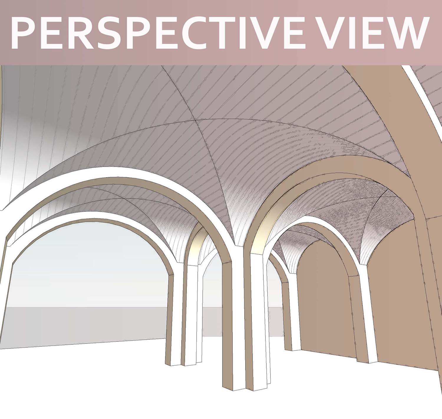
The kind of vault I'm talking about here is a cross-vault, essentially the intersection of two barrel vaults. This post is a review of a family I developed for Project Soane, several years ago. The old Bank of England had a huge sprawling undercroft, divided up into rectangular bays, mostly covered by brick Cross vaults.

I developed a parametric vault capable of adapting to the
many different sizes and shapes represented in this fascinating test case. The
spaces beneath the large Banking Halls typically contain a small forest of
brick pillars within blank perimeter walls. The pillars themselves could be
square, but more often cruciform.

From a Revit point of view, or from a bricklayer's perspective, the space is divided up into cells by a grid of walls. But then it's opened up again by arches that span most of the way from only wall to the next.

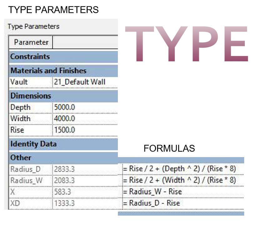
Brick groin vaults (cross vaults) jump across between walls, a little way above the arches. In this case I'm using segmental arches throughout. They are built with parameters for "rise" and "width". Formulas use these parameters to define the radius and the position of the centre point.

The arches have been created as wall-hosted door families. The vaults are standalone Generic Models. Maybe I would put them into ceiling or floor categories if those were available for loadable families.
It takes a little imagination and patience to match the curves of arches and vaults if the spacing of the grid is irregular. Also you may notice that as the proportions of the bays approach long narrow rectangles, the diagonal groin lines twist into "S" shaped curves. If we wanted them to be straight lines on plan, at least one of the arches would need to be elliptical.
The floors above these vaulted cellars were typically paves
with large slabs of York stone. Presumably the spaces above the curved brick
spans was levelled out with rubble, either loose or stabilised with mortar.
Grading down to finer material and topped off with a layer of sand bedding for
the slabs of stone.

In Revit terms I have a rectangular extrusion cut by void sweeps that cross at right angles. The top layers will be a system family. To make all the vaults finish at the same level despite having different spans, I have a parameter to control the thickness of material above the rise of the arch. If the rise drops for some reason I can compensate by increasing this "Xtra Top"

As the work on the Bank of England proceeded I realised that I often needed to extend the vaults on one side, typically around the perimeter, giving the effect of a series of recesses. In the end I had six "Xtra" parameters. To avoid the confusion of too many types I kept all these incremental Xtras as Instance parameters.

I will be going on to review other vault families that I developed in coming weeks. Hope you find this useful. There are shortcomings in this approach. Apart from the S shape in plan there is a problem with material representation. Clearly it would be better to have separate extrusions for the two directions of the intersecting geometry. Finally there could be cases where we don't want the rubble fill. We might want the crowns of the vaults to curve in parallel with the soffits.

To be continued.

Top Brightening Face Wash has a refreshing fragrance and leaves my face feeling soft and glowing after every wash.
ReplyDeleteTop Brightening Face Wash