This is post no 2 of our competition entry. Zach is watching, so behave yourselves.

Pumpkins are well know for their metamorphic properties as Cinderella would be quick to point out. I haven't quite got the coach & horses down yet (still looking for some suitable mice) but the transformations are proceeding apace.

First off was the 20 volute column. Turned out to be quite easy to filter-select and copy-rotate elements to double up the number of points and parameters in my profile. Had to dissolve it first of course and later on select the points, 3 at a time, to do the spline-by-points trick again for each of the 20 volutes.

After that it's a question of creating a parameter for the profile name, so we can choose what to use for base, mid and top. Then associate the radii with parameters R1, R2 & R3 so that I can control the size of each profile from within the host family. Hey presto you get a really nice scaleable Doric column shaft from the same family that made the original pumpkin,

So far this has been done in a Generic Model "Adaptive" family. So it can be converted to another category, EXCEPT for mass. To prove the scaleability I set up another version of the family by loading my profile into a conceptual mass family template. Jack this up to 75 metres high with a base diameter of 10m and we're away.

The base was modelled in-place, mass-floors put in, and then straight on to wall-by-face. Click, click, click go my 20 volutes. I tested out changing the size of the mass family and using "update to face", works fine. Windows go in, copy them up from floor to floor, no problem. Half an hour and I have the basic shell of the building done.
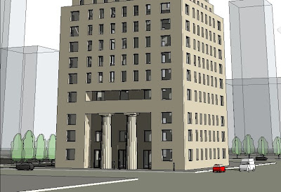
The two doric columns at the main entrance are metamorphosed pumpkins, 3 times over. Confused ? Simple. One for the shaft, one for the echinuus (based on a cirular profile) and one for the abacus (square profile)

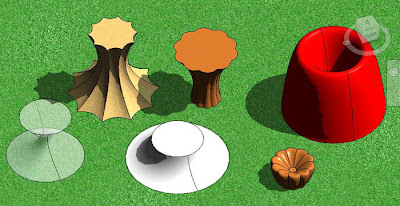
So by now I have 4 different profile families loaded into my pumpkin host, and by playing with parameters I can create all kinds of forms, including re-entrant shapes. And pumpkins of course.

I'll finish with a render of the Tribune scheme by Loos. The windows are not quite right yet, and there should be 28 volutes, not 20. Seems he cheated a bit to get the plan to work. (been there)


If you want to contribute, you can pick up my parametric doric pumpkin family form here.
Anything half decent will get included in my next post.
5 stack pumpkins 2011
Actually this is the 5 profile version, opens with Revit 2011 & later. More about that tomorrow.

Pumpkins are well know for their metamorphic properties as Cinderella would be quick to point out. I haven't quite got the coach & horses down yet (still looking for some suitable mice) but the transformations are proceeding apace.

First off was the 20 volute column. Turned out to be quite easy to filter-select and copy-rotate elements to double up the number of points and parameters in my profile. Had to dissolve it first of course and later on select the points, 3 at a time, to do the spline-by-points trick again for each of the 20 volutes.

After that it's a question of creating a parameter for the profile name, so we can choose what to use for base, mid and top. Then associate the radii with parameters R1, R2 & R3 so that I can control the size of each profile from within the host family. Hey presto you get a really nice scaleable Doric column shaft from the same family that made the original pumpkin,

So far this has been done in a Generic Model "Adaptive" family. So it can be converted to another category, EXCEPT for mass. To prove the scaleability I set up another version of the family by loading my profile into a conceptual mass family template. Jack this up to 75 metres high with a base diameter of 10m and we're away.

The base was modelled in-place, mass-floors put in, and then straight on to wall-by-face. Click, click, click go my 20 volutes. I tested out changing the size of the mass family and using "update to face", works fine. Windows go in, copy them up from floor to floor, no problem. Half an hour and I have the basic shell of the building done.

The two doric columns at the main entrance are metamorphosed pumpkins, 3 times over. Confused ? Simple. One for the shaft, one for the echinuus (based on a cirular profile) and one for the abacus (square profile)

So by now I have 4 different profile families loaded into my pumpkin host, and by playing with parameters I can create all kinds of forms, including re-entrant shapes. And pumpkins of course.

How about egg-cups, golf tees, crown-of-thorn cathedrals ... lots of possibilities here
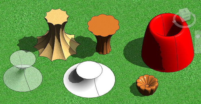

I guess you could count the windows as "carving", but I'd like to do some parametric voids that do clever stuff. Any ideas ?

If you want to contribute, you can pick up my parametric doric pumpkin family form here.
Anything half decent will get included in my next post.
5 stack pumpkins 2011
Actually this is the 5 profile version, opens with Revit 2011 & later. More about that tomorrow.


