Last night we were at the Middle East Architect awards ceremony, held on the Palm Jumeirah, which is a short taxi ride from our offices. We had entered several categories and came away with 4 second places plus one outright winner.

Appropriately it was our boss, Brian Johnson who won : Principal of the Year 2011, in recognition of 30 years of outstanding work in the Region, including one of Dubai's first iconic buildings, the Creek Golf Club, which features on the 20 Dirham note. Not so many architectural practices who can hand out bank notes as business cards :)

This year there was a new category: BIM Project of the Year, and I am proud to say that we earned a "Highly Commended" second place for the work my Revit team has done on Saray Bandar Jissah in Oman. A big thank you for all the guys & gals on the team for all the effort they have put in over the past year on this challenging project.

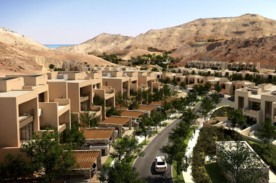
This is a residential resort with about 350 villas, a short drive from Muscat . Advanced earthworks are due to start later this year. The setting is quite dramatic with jagged mountain ridges and valleys leading to an unspoilt beach on the India Ocean. Our Revit work ranged from Strategic Masterplanning to meticulous detailing of bathroom layouts.
We have a complex set of cross-linked and nested files in order to handle the complexity of the site within our hardware constraints. All the villas have 2 versions: the full villa with all the CD sheets and a simplified massing model, sufficient for most masterplanning exercises. We swop these links in and out as needed. There is a file for the overall topography, with holes cut in it for each group of villas. Typically we have 10 or 12 villas in each zone file, where we model all the platform levels, the cut and fill, the landscaping, streel lights etc.

The infrastructure engineers issue their drawings in separate packages arranged by sub-discipline. The Revit model has really helped us to see how the earthworks, surface drainage, retaining walls, etc fit together in 3 dimensions. In many cases of course they don't fit together, and very rarely do they take into account the architectural and landscape design requirements, partly because their work had to be completed far in advance of ours, so they are always trying to finalise things before we have been able to develop our designs properly.

Conversely the landscape designers are a couple of steps behind us and often only have 2 dimensional concept sketches, when we really need to finalise ground shaping levels with the engineers. Our masterplanning model has been a fantastic tool for highlighting critical issues that need to be resolved and obtaining sign-off of the decisions that matter so that the engineers can complete their tender package and the landscape guys know the parameters whithin which they will have to work when they move to detailed design.

At a smaller scale we have had to develop a strategy that allows a mass concrete marine wall to be built 2 years in advance to a pool specialist coming on site to construct infinity edge pools that overlook a salt-water lagoon. Once again it was essential to be able to visualise relationships between different elements owned by multiple stakeholders in the design team, and to think about sequences of operations. Revit has a great ability to duplicate views and hide elements so that you can simulate a construction sequence. The section box views are also crucial to this kind of coordination exercise.


Appropriately it was our boss, Brian Johnson who won : Principal of the Year 2011, in recognition of 30 years of outstanding work in the Region, including one of Dubai's first iconic buildings, the Creek Golf Club, which features on the 20 Dirham note. Not so many architectural practices who can hand out bank notes as business cards :)

This year there was a new category: BIM Project of the Year, and I am proud to say that we earned a "Highly Commended" second place for the work my Revit team has done on Saray Bandar Jissah in Oman. A big thank you for all the guys & gals on the team for all the effort they have put in over the past year on this challenging project.

This is a residential resort with about 350 villas, a short drive from Muscat . Advanced earthworks are due to start later this year. The setting is quite dramatic with jagged mountain ridges and valleys leading to an unspoilt beach on the India Ocean. Our Revit work ranged from Strategic Masterplanning to meticulous detailing of bathroom layouts.

We have a complex set of cross-linked and nested files in order to handle the complexity of the site within our hardware constraints. All the villas have 2 versions: the full villa with all the CD sheets and a simplified massing model, sufficient for most masterplanning exercises. We swop these links in and out as needed. There is a file for the overall topography, with holes cut in it for each group of villas. Typically we have 10 or 12 villas in each zone file, where we model all the platform levels, the cut and fill, the landscaping, streel lights etc.

The infrastructure engineers issue their drawings in separate packages arranged by sub-discipline. The Revit model has really helped us to see how the earthworks, surface drainage, retaining walls, etc fit together in 3 dimensions. In many cases of course they don't fit together, and very rarely do they take into account the architectural and landscape design requirements, partly because their work had to be completed far in advance of ours, so they are always trying to finalise things before we have been able to develop our designs properly.

Conversely the landscape designers are a couple of steps behind us and often only have 2 dimensional concept sketches, when we really need to finalise ground shaping levels with the engineers. Our masterplanning model has been a fantastic tool for highlighting critical issues that need to be resolved and obtaining sign-off of the decisions that matter so that the engineers can complete their tender package and the landscape guys know the parameters whithin which they will have to work when they move to detailed design.

At a smaller scale we have had to develop a strategy that allows a mass concrete marine wall to be built 2 years in advance to a pool specialist coming on site to construct infinity edge pools that overlook a salt-water lagoon. Once again it was essential to be able to visualise relationships between different elements owned by multiple stakeholders in the design team, and to think about sequences of operations. Revit has a great ability to duplicate views and hide elements so that you can simulate a construction sequence. The section box views are also crucial to this kind of coordination exercise.

For the bathrooms I went onto the Duravit & Hansgrohe sites to download 3d CAD models of the selected fittings and incorporated these into Revit families. Often these familes contain 3 or 4 nested components pre-configured into their correct relationships (toilet pan, TRH, push plate, hand spray, cistern boxing) If the relationships change, the families can be reloaded into the 50 or so bathroom types in the project to maintian consistency with very little effort. This is where the the "revise instantly" origin of the Revit name is vindicated.

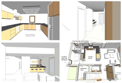
Kitchens were done to similar level of detail, and our client put us through 3 or 4 design iterations, all presented in cutaway perspective views as well as traditional plans & elevations for each of the dozen or so kitchen types.

I'll try to do a more detailed post on some of the families we developed for this project soon, but to conclude here's a rendering of one of the villas done directly from the Revit model

That was great!
ReplyDeletethanks for sharing!
how you attach walles to base , such as toposurface?
ReplyDeleteDid you use base or high offset ?
The toposurface is really huge and it has diffrent hight!
How you solve these problems?
Best regards
Great write up Andy. I've been flicking back and forth between images 5 & 6 trying to work out how the siteworks were modelled. It's not topo. Masses? Or a heavily modified floor?
ReplyDeleteThe earthworks platforms were generally modelled in place as extrusions, sweeps, swept blends. Some use of void cuts also. Split surfaces were used to approximate the boundaries between cut and fill. We created the toposurface for the mountains from CAD survey contours and then cut out the areas where the villas are to be built. We kept the original contours as a file that can be loaded in when needed and made the material semi-transparent so you can see where it intersects the platforms. Extrusions are easier to adjust than pads and you don't get nasty things happening when two edges don't quite align.
ReplyDeleteSound workflow and one I'm trying to get through to my team on a site nearly the size of yours (all be it less densely built on, and on far flatter terrain) - but I'm reaching two hurdles; one the lack of experience with the mass tools (that'll right themslves in time) and two, an expectation that Revit "should" do it all (that'll just go round and round and round...)
ReplyDeleteKeep up the good work!
(Kieren / "snowyweston" @RFO/Augi/etc)
Thanks Kieren. It was a pretty steep learning curve for us, and pretty much figuring out as we went along. My guys learnt a lot about the basic modelling tools on the way and I gained a much greater insight into using the topo tools. Spent a fair bit of time shaping the spaces between groups of plots which were rather harshly engineered when I first joined the project, largely because it wall all in 2d and people hadn't really grasped the impact of the civil engineers proposals.
ReplyDeleteThis comment has been removed by the author.
ReplyDelete