Another weekend, and looking forward to preparing more packaged tasks for collaborators on Project Soane to tackle. First off I checked out the Box folder where all the shared reference material resides along with the families we are currently working on. I knew from a Slack message that the large lunette windows of the Central Hall had been updated with glazing bars in a radial pattern, so I loaded this family back into the main model on C4R

At first glance it looks fine, but zooming in I notice that the glazing bars have come adrift from the glass. Opening it up in Family Editor, everything seems fine, but of course the wall thickness is not the same, so change this from 6" to 12" and you reproduce the issue in the main model.

Easy to fix, just associate the sweeps with an appropriate work plane ... but no, that option is not available. Edit sweep and it's clear that the path was created using "pick 3d edges". I had advocated drafting this pattern out in lines to get the proportions right, then proceeding to model sweeps. Hadn't thought about discussing the difference between model lines and symbolic lines, or the two ways of picking a line to generate a sweep path.

Problem is that the model lines that were "picked" to generate the paths have now been deleted. They would originally have been drawn on a plane. Going into a side there is a plane called "Glass Surface" which seems to be the one, so I tried a bit of reverse logic, associating the frame and glass with this plane and adjusting their start and end offsets

Now I can also add a "setback" parameter to move the plane and the geometry should move along with it, allowing us to adjust the position of the window within the thickness of the wall.

Forlorn hope. The sweeps have no idea that they were once tied to this plane via model lines that are long gone. Even if you lock the geometry to the plane it's not happy. Breaks as soon as you change the setback.

Never mind. let's just lock that parameter at 4" and load it back. Well it's fine on one side, but the wall on the other side is a different thickness for whatever reason and the glazing bars are floating off into space again.

So there's no option really but to create new sweeps. (You can't convert a 3d pick into a sketch.) So I set myself up to draw symbolic lines as a guide. Going into Object Styles I chose the last subcategory and set it to Red, then started drawing. It soon became apparent that there were deeper issues to be dealt with.
The smallest arc is not concentric with the others, and all of the arc centres are well below the sill line. This comes from my original setting out of the opening size and shape over a year ago. Didn't seem to be problematic until we added the glazing bars.

This space has a groin vault in the middle, and shallow barrel vaults (or deep arches if you prefer) at the sides. The sides are formed by a wall hosted family which includes the Ionic columns.
I think perhaps I created this before I had fully defined the entablature profile. Probably this got deeper when I looked at the source material more carefully and this meant cutting about 3 inches off the bottom of the window. So I decided to raise all the vaults by 3" and adjust the window to match.
The groin vault just moves up. Increase its offset value.

The wall hosted arch family needs more work. I noticed that there is a parameter for the shoulder height (springing point) of the arch, but adjusting this creates a gap above the Ionic capital. Edit the opening cut to compensate, and while I'm at it, why not add a locked reference plane to keep this stationary while "Shoulder Ht" flexes?

All fine now, with a wider margin above the window ready for it to be updated. That's easily achieved by editing the void cut, frame and glass: moving the arc segments up 3" in each case. No parameters to worry about, it's intended as a one-off family, fixed size. Now I can start sketching.


The reference photo we have is difficult to interpret. Seems like extra glazing bars have been added and viewed from below the bottom is cut off and the perspective skewed. I decided to take a look at the Dividend Office, which has similar glazing pattern. Here we have 9 radial divisions, which is easy: 20 degrees each.

But in the Centre Hall, we have 7. After a bit of trial and error I voted for 5 x 25 degrees, with larger angles at the ends, next to the sill. This compensates for the thickness of the outer frame. So I set out a kind of skeletal framework, using drafting lines in 2d space. Actually a spider's web seems to be a better metaphor.

Now to build sweeps. Instead of using Pick Path, which would base the work plane on a picked 3d object, I go for Sketch Path. Not to worry t

here is still a pick option at the next step. But now the path is not tied to the object that was picked, so the resulting sweep can be associated with a new work plane later on if you so desire.
My desire is to use the aforementioned "Glass Surface" ref plane ... which is already controlled by instance parameter "Setback". I opted for instance because the walls at either side of the room that host these windows have different thicknesses. Easy for me to adjust the location of each window relative to the wall faces.

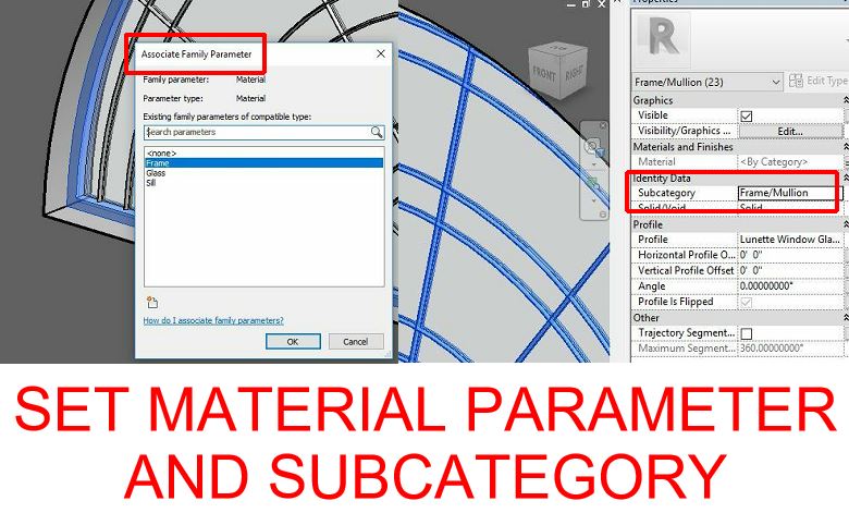
I created the first radial bar, made its subcategory "Frame/Mullion", associated it with a material parameter, then mirrored it around using the red lines as reflection planes. Copy one of these to one side, edit path, pick a curve and delete the straight line. Slightly faster than creating a new sweep from scratch, because the subcategory and material are already defined.

Before completing the entire pattern I decide to test it out in the project environment. Load it up, change the setback, all good. And now it strikes me that my job is done. I can save it back into the Box folder, write up a little post and let my collaborator finish it off. I'm quite chuffed because I'm now seeing Project Soane as a useful vehicle for teaching basic Family Editor skills and sharing that process with the wider Revit community.

There are lots of interesting challenges here and they will surely generate all kinds of interesting topics for blog posts. That's what I've been doing since the beginning of course, but the difference here is that I'm starting to see things through the eyes of someone less experienced. That's the value of a collaborative team with different skill levels. It's bound to throw up examples of knowledge sharing that will be useful to others. Oh, and don't forget to test the Setback parameter.

By the way, notice the shadows on the wall. Soane was master of effects of light and those spider's webs drifting across the moulded plaster panels must have delighted him.


At first glance it looks fine, but zooming in I notice that the glazing bars have come adrift from the glass. Opening it up in Family Editor, everything seems fine, but of course the wall thickness is not the same, so change this from 6" to 12" and you reproduce the issue in the main model.

Easy to fix, just associate the sweeps with an appropriate work plane ... but no, that option is not available. Edit sweep and it's clear that the path was created using "pick 3d edges". I had advocated drafting this pattern out in lines to get the proportions right, then proceeding to model sweeps. Hadn't thought about discussing the difference between model lines and symbolic lines, or the two ways of picking a line to generate a sweep path.

Problem is that the model lines that were "picked" to generate the paths have now been deleted. They would originally have been drawn on a plane. Going into a side there is a plane called "Glass Surface" which seems to be the one, so I tried a bit of reverse logic, associating the frame and glass with this plane and adjusting their start and end offsets

Now I can also add a "setback" parameter to move the plane and the geometry should move along with it, allowing us to adjust the position of the window within the thickness of the wall.

Forlorn hope. The sweeps have no idea that they were once tied to this plane via model lines that are long gone. Even if you lock the geometry to the plane it's not happy. Breaks as soon as you change the setback.

Never mind. let's just lock that parameter at 4" and load it back. Well it's fine on one side, but the wall on the other side is a different thickness for whatever reason and the glazing bars are floating off into space again.

So there's no option really but to create new sweeps. (You can't convert a 3d pick into a sketch.) So I set myself up to draw symbolic lines as a guide. Going into Object Styles I chose the last subcategory and set it to Red, then started drawing. It soon became apparent that there were deeper issues to be dealt with.
The smallest arc is not concentric with the others, and all of the arc centres are well below the sill line. This comes from my original setting out of the opening size and shape over a year ago. Didn't seem to be problematic until we added the glazing bars.

This space has a groin vault in the middle, and shallow barrel vaults (or deep arches if you prefer) at the sides. The sides are formed by a wall hosted family which includes the Ionic columns.
I think perhaps I created this before I had fully defined the entablature profile. Probably this got deeper when I looked at the source material more carefully and this meant cutting about 3 inches off the bottom of the window. So I decided to raise all the vaults by 3" and adjust the window to match.
The groin vault just moves up. Increase its offset value.

The wall hosted arch family needs more work. I noticed that there is a parameter for the shoulder height (springing point) of the arch, but adjusting this creates a gap above the Ionic capital. Edit the opening cut to compensate, and while I'm at it, why not add a locked reference plane to keep this stationary while "Shoulder Ht" flexes?

All fine now, with a wider margin above the window ready for it to be updated. That's easily achieved by editing the void cut, frame and glass: moving the arc segments up 3" in each case. No parameters to worry about, it's intended as a one-off family, fixed size. Now I can start sketching.


The reference photo we have is difficult to interpret. Seems like extra glazing bars have been added and viewed from below the bottom is cut off and the perspective skewed. I decided to take a look at the Dividend Office, which has similar glazing pattern. Here we have 9 radial divisions, which is easy: 20 degrees each.

But in the Centre Hall, we have 7. After a bit of trial and error I voted for 5 x 25 degrees, with larger angles at the ends, next to the sill. This compensates for the thickness of the outer frame. So I set out a kind of skeletal framework, using drafting lines in 2d space. Actually a spider's web seems to be a better metaphor.

Now to build sweeps. Instead of using Pick Path, which would base the work plane on a picked 3d object, I go for Sketch Path. Not to worry t

My desire is to use the aforementioned "Glass Surface" ref plane ... which is already controlled by instance parameter "Setback". I opted for instance because the walls at either side of the room that host these windows have different thicknesses. Easy for me to adjust the location of each window relative to the wall faces.

I created the first radial bar, made its subcategory "Frame/Mullion", associated it with a material parameter, then mirrored it around using the red lines as reflection planes. Copy one of these to one side, edit path, pick a curve and delete the straight line. Slightly faster than creating a new sweep from scratch, because the subcategory and material are already defined.
Before completing the entire pattern I decide to test it out in the project environment. Load it up, change the setback, all good. And now it strikes me that my job is done. I can save it back into the Box folder, write up a little post and let my collaborator finish it off. I'm quite chuffed because I'm now seeing Project Soane as a useful vehicle for teaching basic Family Editor skills and sharing that process with the wider Revit community.

There are lots of interesting challenges here and they will surely generate all kinds of interesting topics for blog posts. That's what I've been doing since the beginning of course, but the difference here is that I'm starting to see things through the eyes of someone less experienced. That's the value of a collaborative team with different skill levels. It's bound to throw up examples of knowledge sharing that will be useful to others. Oh, and don't forget to test the Setback parameter.

By the way, notice the shadows on the wall. Soane was master of effects of light and those spider's webs drifting across the moulded plaster panels must have delighted him.

Andy, thanks for the blog post! I always read your articles with great pleasure!
ReplyDeleteYou are right, such "analysis" of families will be good practice.
I think it would be great to have a link to the family in its original state, for training.
Also, it would be cool at the end of the post as the resume add a few conclusions about how to properly organize work with the family.
For example: check a family based on a wall not only by changing the size, but also by changing the wall thickness in the family; Use an additional work plane for the impost and frame ...
Thanks again.
Hey Dmitry, good suggestions! Thanks for the feedback.
ReplyDeletethank for the wonderful post , lots of information gained , visit us Revit Modeling in India
ReplyDelete